PLC OMRON CP1E | CARA PASANG INPUT OUTPUT

JAGO LISTRIK
18 Jun 202305:19

Summary

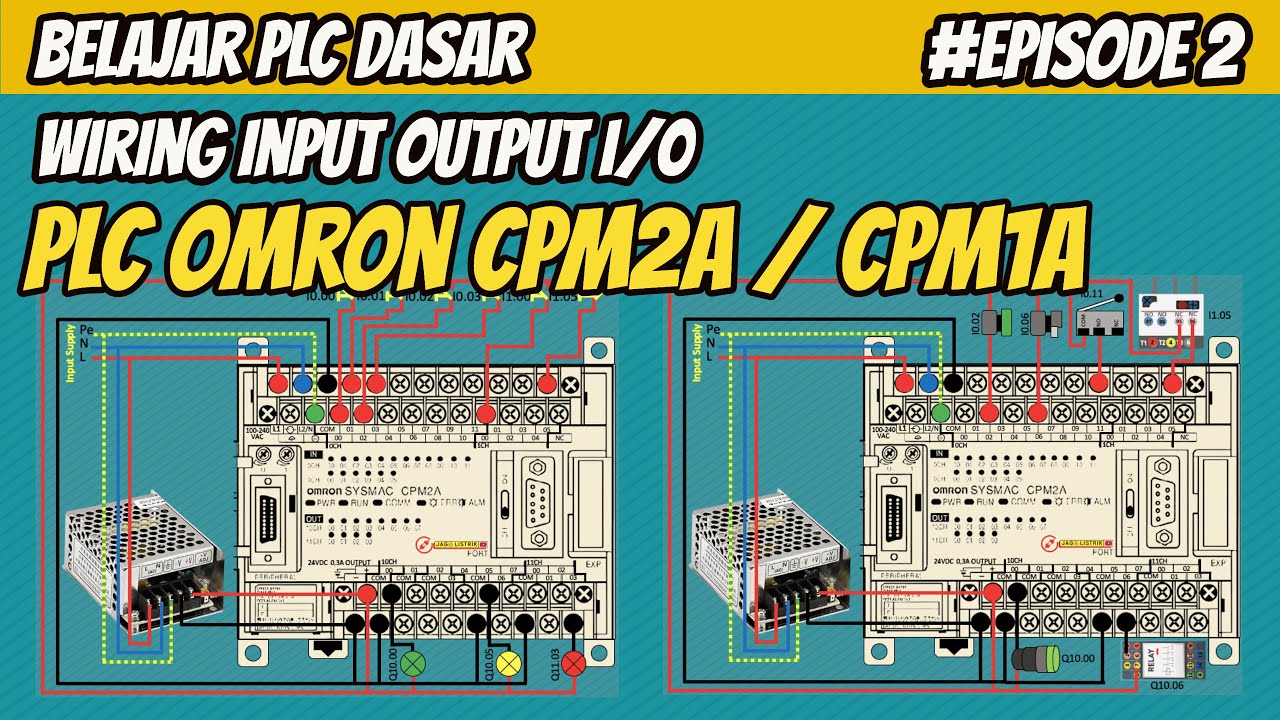
TLDRThis video tutorial from the 'jago listrik' channel focuses on the installation of input and output components for the Omron CP1E PLC. It explains that inputs are typically on top and outputs below, with the unique requirement for a DC 24-volt supply instead of the usual AC. The presenter demonstrates how to convert 220-volt AC from the power supply to the necessary DC voltage using a power supply unit. The video also covers wiring the input and output components, highlighting the connection of a common (COM) terminal for all inputs and separate COM terminals for different output ranges, ensuring viewers understand the setup for the Omron CP1E PLC.

Takeaways

  • 🔌 The video discusses the installation of input and output components on an Omron CP1E PLC.
  • 📌 Inputs are typically placed above and outputs below on the PLC, with the supply input voltage being a key consideration.
  • ⚡ The Omron CP1E uses DC voltage for inputs, specifically 24 volts DC, differing from the common AC voltage used in other PLCs.
  • 🔄 A power supply unit is necessary to convert 220 Volt AC from the mains to the required 24 Volt DC for the PLC.
  • 🔗 The wiring of the power supply involves connecting the LN (Line) and ground to the AC source and the output to the PLC's positive and negative terminals.
  • 🔩 The input components, such as push buttons, are connected to the DC power supply's positive voltage, while the common (COM) terminal is connected to the negative voltage.
  • 🔑 A single COM terminal is used for all inputs, simplifying the wiring process for inputs.
  • 💡 The video provides a practical example of connecting a normally closed (NC) push button to an input address and an output to a specific address.
  • 🔑 For outputs, each set of outputs has its own COM terminal, which is different from the input's single COM terminal setup.
  • 🛠️ The video explains how to wire outputs to the corresponding output addresses on the PLC, with each output having its own designated address.
  • ❓ The presenter invites viewers to ask questions in the comments if they need further clarification.

Q & A

  • What is the main topic discussed in the video?

    -The main topic discussed in the video is the installation of input and output components on an Omron CP1E PLC.

  • What is the difference between the input voltage for Omron CP1E PLC and other PLCs?

    -The Omron CP1E PLC uses a DC voltage of 24 volts for its inputs, unlike other PLCs which typically use AC voltage for inputs.

  • Why is it necessary to convert AC voltage to DC for the Omron CP1E PLC?

    -It is necessary to convert AC voltage to DC for the Omron CP1E PLC because its input components require a DC voltage of 24 volts.

  • What is the role of a power supply in the setup described in the video?

    -The power supply is used to convert the AC voltage from the mains (220 Volt AC) to the required DC voltage (24 Volt DC) for the PLC's input components.

  • How are the input components connected to the Omron CP1E PLC?

    -The input components are connected to the Omron CP1E PLC by linking the common (COM) terminal to the negative polarity of the DC power supply and connecting the input devices to the positive DC voltage.

  • What is the purpose of the COM terminal in the context of the video?

    -The COM terminal is used as a common connection point for all input addresses from 00 to 11, allowing a single COM connection for all inputs.

  • How does the wiring for input components differ from output components on the Omron CP1E PLC?

    -For input components, there is only one COM for all input ports, whereas for output components, there are multiple COMs (1, 2, 3, and 4), each serving different ranges of output addresses.

  • What is the significance of the thick white line mentioned in the video?

    -The thick white line signifies the limit for each output COM, indicating that each output has its own dedicated COM terminal and should not be mixed with others.

  • How are the output components connected to the Omron CP1E PLC?

    -The output components are connected by linking the respective COM terminal to the negative polarity of the DC power supply and connecting the load or device to the corresponding output port.

  • What is the address format for outputs on the Omron CP1E PLC as described in the video?

    -The address format for outputs on the Omron CP1E PLC is 'Q' followed by the slot number and the channel number, such as Q100.00 for output 00.

  • What does the video suggest for viewers who are not clear about the content?

    -The video suggests that viewers who are not clear about the content can leave a comment below for further clarification.

Outlines

00:00

🔌 Installation of Input/Output Components on Omron CP1E PLC

This paragraph discusses the installation of input and output components on the Omron CP1E PLC. The presenter explains that inputs are typically placed above and outputs below. A crucial point to note is that the input voltage for this PLC model is DC, specifically 24 volts DC, differing from the usual AC input voltage in PLCs. To match this requirement, a power supply is needed to convert the standard 220-volt AC from the power grid to 24 volts DC. The wiring for the power supply involves connecting the LN and ground to the AC source and the output to the PLC's positive and negative terminals. For the input components, a common (COM) terminal is used for all inputs from 00 to 11, connected to the negative DC voltage. An example given is connecting a normally closed (NC) push button to the positive DC voltage and the output push button to an output address, such as 01, which corresponds to the address i1001. The process is straightforward and helps in understanding how to set up the input components for the Omron CP1E PLC.

05:02

🔗 Wiring Techniques for Omron CP1E PLC's Input and Output

The second paragraph continues the discussion on the wiring of the Omron CP1E PLC, focusing on the output components. Unlike the single common terminal for all input ports, the outputs have multiple common terminals, each serving different output ranges. For instance, one common terminal is for output 00, another for outputs 01 to 03, and so on, up to output 07. Each output has its own common terminal, which is limited by a thick white line on the PLC. The wiring process for the outputs is similar to that of the inputs, connecting the common terminal to the negative voltage of the power supply. The presenter uses examples to illustrate how to connect a light or load to the output ports, such as connecting a light to the positive voltage of the power supply and the other side to an output port like 00, which corresponds to the address q100.00. The paragraph concludes with an invitation for viewers to ask questions in the comments if they need further clarification and a promise to meet again in the next video.

Mindmap

Keywords

💡PLC

PLC stands for Programmable Logic Controller, which is a digital operational technology used in industrial automation and control systems. In the video, the presenter discusses the installation of input and output components on an Omron CP1E PLC, indicating that PLCs are the central theme of the tutorial. The Omron CP1E is a specific model of PLC used for various automation tasks.

💡Input

In the context of PLCs, 'input' refers to the signals or data that are fed into the system from external devices such as sensors or switches. The script mentions that inputs are always on top, and they are connected to a common (COM) terminal for all inputs from 00 to 11, which is a standard practice in PLC wiring to establish a reference point for the input signals.

💡Output

An 'output' in PLC terminology is the signal that the PLC sends to control external devices such as motors or indicators. The video script explains that outputs are located below the inputs and each output has its own common (COM) terminal, which is essential for understanding how to wire devices to the PLC for controlling them.

💡Omron CP1E

The Omron CP1E is a specific model of PLC discussed in the video. It is highlighted as the subject of the tutorial, where the presenter is explaining how to install input and output components on this particular model. This keyword is crucial as it sets the context for the technical discussion in the video.

💡Power Supply

A power supply in this context is a device that converts AC voltage from the mains to the DC voltage required by the PLC. The script specifies that the Omron CP1E requires a 24-volt DC power supply, and the presenter explains how to wire the power supply to the PLC, which is a critical step in the setup process.

💡DC Voltage

DC, or direct current, voltage is the type of electrical energy used by the Omron CP1E PLC as per the video. The presenter emphasizes that the input voltage for this PLC is 24 volts DC, which contrasts with AC voltage typically used in household power. Understanding DC voltage is key to knowing how to properly power the PLC.

💡Wiring

Wiring in the context of the video refers to the physical connections made between the PLC and its input/output devices. The presenter provides a detailed explanation of how to wire the power supply, inputs, and outputs, which is essential for anyone looking to set up or understand the physical connections in a PLC system.

💡Push Button

A push button is a type of input device that is mentioned in the script as an example of an input component. It is used to send signals to the PLC when pressed. The video explains how to wire a push button to the PLC, which is a common practice in industrial control systems for initiating processes or providing user inputs.

💡Common (COM)

In the context of the video, 'common' or 'COM' refers to a terminal on the PLC where all inputs or outputs are connected to a common reference point. The script explains that there is one COM for all inputs and separate COMs for different groups of outputs, which is a fundamental concept in PLC wiring for establishing circuits.

💡Polarity

Polarity in electronics refers to the positive and negative terminals of a power source. The video script mentions connecting the V+ to the positive terminal of the PLC and the ground to the negative, which is crucial for ensuring that the PLC and its components are powered correctly and safely.

💡Address

An 'address' in PLC programming is a unique identifier for each input and output. The script provides examples of how to determine the address for inputs (I1001) and outputs (Q100.00) based on their wiring to the PLC. Understanding addresses is essential for programming and troubleshooting PLC systems.

Highlights

Introduction to Omron CP1E PLC and its components setup

Explanation of input and output component placement on the PLC

Note on the standard placement of inputs above and outputs below on PLCs

Emphasis on the importance of matching input voltage to the PLC version

Clarification that Omron CP1E uses DC 24V for inputs, differing from typical AC inputs

Requirement to convert AC 220V to DC 24V for the PLC

Use of a power supply to convert AC to DC voltage

Wiring instructions for the power supply to connect to AC source

Connection of DC output to the PLC's positive and negative terminals

Simplification of input wiring with a single common (COM) for all inputs

How to wire a push button as an input to the DC positive voltage

Connecting the output of a push button to a specific output address on the PLC

Method for observing the input to help with subsequent output connections

Difference in wiring for outputs compared to inputs, with multiple COMs for different output ranges

Connection of the COM to the negative power supply voltage

Wiring a light to the DC positive voltage and connecting the load to the output port

Addressing of the output based on the used COM and output port

Encouragement for viewers to ask questions in the comments for further clarification

Transcripts

play00:00

kembali lagi di channel jago listrik

play00:01

kali ini kita akan membahas tentang

play00:03

versi lagi nih teman-teman tepatnya PLC

play00:06

Omron cp1e penampakannya seperti ini

play00:10

jadi kali ini saya akan menjelaskan

play00:12

Bagaimana pemasangan komponen input

play00:15

output pada PLC cp1e ini teman-teman

play00:18

menggunakan ilustrasi Oke kita langsung

play00:21

aja nah seperti versi-versi sebelumnya

play00:25

yang saya jelaskan input selalu di atas

play00:28

sedangkan output itu di bawah nah yang

play00:31

perlu diperhatikan pada setiap versi

play00:33

apapun mereknya itu adalah supply input

play00:37

tegangan ke versinya teman-teman nah

play00:40

pada penjelasan saya yang sebelumnya itu

play00:43

rata-rata input tegangan plc-nya

play00:45

tegangan AC ya teman-teman Nah berbeda

play00:48

dengan versi Omron cp1i ini pada versi

play00:52

ini inputnya adalah tegangan DC tepatnya

play00:56

24 volt DC jadi supaya sesuai dengan ke

play01:01

versi ini harus 24 volt sih teman-teman

play01:04

Nah karena ini memerlukan tegangan DC

play01:07

jadi kita harus merubah dulu tegangan

play01:09

PLN 220 Volt AC ke tegangan DC 24 volt

play01:15

ya teman-teman Nah caranya gimana kita

play01:17

bisa menggunakan power supply ya Nah

play01:20

power supply ini berfungsi untuk merubah

play01:22

tegangan AC ke tegangan DC nah cara

play01:25

wiring power supply ini seperti ini pada

play01:28

kode LN dan ground itu kita hubungkan ke

play01:31

sumber tegangan AC atau PLN ya 220 Volt

play01:35

AC l itu fasa and Itu netral dan

play01:37

sebelahnya itu ground sedangkan

play01:40

outputnya itu berupa DC teman-teman ada

play01:42

feminin V plus nah V plus itu polaritas

play01:45

plus dan feminin polaritas Min nah ini

play01:48

kita hubungkan yang V plus ke plusnya

play01:51

PLC dan PMI ke femininnya versi nah

play01:54

seperti ini plus ke plus - teman-teman

play01:57

sedangkan ground-nya langsung yang ada

play01:59

lambang groundnya nah bagaimana dengan

play02:01

komponen inputnya nah ini simpel aja

play02:03

kalau kita lihat di sini ada com ya

play02:06

teman-teman com ini tepat masukkan untuk

play02:08

semua alamat input dari

play02:11

00 sampai 11 Jadi cukup satu com untuk

play02:14

semua input nah ini kita hubungkan dulu

play02:17

com ini ke tegangan DC yang polaritas

play02:21

minus seperti ini Nah ini teman-teman

play02:23

bisa ambil dari minus atau langsung dari

play02:26

minusnya power supply ya teman-teman

play02:29

setelah ini kita bisa langsung memasang

play02:31

komponen inputnya nah contohnya berupa

play02:34

push button NC bagian input button kita

play02:37

hubungkan ke tegangan plus dc-nya

play02:41

sedangkan yang output push button kita

play02:45

hubungkan ke alamat output 01 contohnya

play02:47

nah ini terserah teman-teman

play02:49

menghubungkan yang mana Kebetulan saya

play02:51

di sini 01 maka alamatnya

play02:55

i1001 begitu cara pengamatan inputnya

play02:59

membantu output selanjutnya sama saja

play03:01

seperti ini contohnya push button NU

play03:03

yang atasnya kita ambil dari polaritas

play03:06

plus tegangan DC power supply silahkan

play03:08

yang bawahnya langsung kita hubungkan ke

play03:10

port inputnya yang 08 jadi alamatnya

play03:16

i10.08 begitu teman-teman Gampang ya Nah

play03:19

selanjutnya yang outputnya ada perbedaan

play03:22

sedikit input 1com untuk semua port

play03:26

inputnya sedangkan pada output itu ada

play03:29

beberapa com ada 1 2 3 dan 4 nahkom ini

play03:32

untuk output 00 sedangkan com ini untuk

play03:35

output 01 com yang ini untuk output 0203

play03:38

sedangkan com ini untuk output 04 sampai

play03:41

07 jadi setiap output mempunyai gomnya

play03:45

sendiri nah ini dibatasi oleh garis

play03:48

tebal putih ini teman-teman nah cara

play03:50

menghubungkannya sama seperti input

play03:52

comnya kita hubungkan ke polaritas

play03:54

negatif power supply-nya tegangannya nah

play03:58

seperti ini

play03:59

nah Kebetulan saya memakai com yang ini

play04:01

jadi output ya saya pakai yang nol

play04:04

teman-teman nah seperti ini

play04:07

Nah jadi lampu sehubungkan ke tegangan

play04:11

DC prioritas + power supplynya sedangkan

play04:14

bagian Sisi satunya beban atau lampu

play04:18

saya hubungkan ke port output 00 nya

play04:22

karena saya memakai com yang ini jadi

play04:24

alamatnya bisa seperti ini

play04:29

q100.00 nah output berikutnya sama saja

play04:32

misalkan Saya memakai com yang ini ya

play04:34

teman-teman Yang ini sama kita ambil

play04:37

dari negatifnya tegangan DC Nah jadi

play04:41

saya harus memakai output 02 atau 03

play04:44

atau kedua-duanya ya teman-teman Nah di

play04:47

sini Saya memakai yang 03 maka alamatnya

play04:52

q100.03 itu juga selanjutnya

play04:55

Saya memakai Komeng ini jadi saya

play04:57

memakai output 04 sampai 06 ya Nah

play05:01

seperti ini saya pakai yang 06 jadi

play05:04

q100.06 nah begitu caranya wiring input

play05:08

dan output pada versi obrolan cv1e ini

play05:12

teman-teman Nah bagi teman-teman yang

play05:13

belum paham bisa komen bawah dan sampai

play05:15

jumpa di video selanjutnya see you

play05:18

teman-teman

Rate This

5.0 / 5 (0 votes)

Étiquettes Connexes
PLC InstallationOmron CP1EElectrical TutorialDC Power SupplyInput OutputWiring BasicsIndustrial AutomationTechnical GuideEducational VideoDIY Electronics
Besoin d'un résumé en anglais ?