N bit Multiplier in Verilog (with code)| Verilog Project | Xilinx Vivado | Electronics Project
Summary
TLDRIn this wavelog project, Arjun Narula introduces an n-bit multiplier with a binary to BCD converter. The video demonstrates creating an n-bit multiplier using the shift and add algorithm, converting the binary result to BCD with the double-dabble method. The process is illustrated with a flowchart and Verilog code, showcasing the multiplication of two eight-bit numbers and the conversion of the result to a 16-bit BCD. Test benches are included to verify the functionality with examples, and resources for further learning are provided in the description.
Takeaways
- 😀 The video is a tutorial by Arjun Narula on creating an n-bit multiplier with a binary to BCD converter.
- 📈 The project involves building an n-bit multiplier using the shift and add algorithm, with the result being in binary form.
- 🔄 The binary result is then converted to BCD (Binary-Coded Decimal) using the double-dabble algorithm.
- 📑 The video script provides a step-by-step explanation of converting a binary number to BCD, using the number 151 as an example.
- 💡 A key statement for the double-dabble algorithm is provided: if the number is greater than four, add three and shift; otherwise, just shift.
- 🛠️ The flowchart of the problem is discussed, detailing the process from reset to multiplication and BCD conversion.
- 🔢 The script mentions a parameterized n-bit multiplier, where 'n' can be any value, with an example using n as 8 bits.
- 📝 The Verilog code for the project is available in the video description, and the video includes a test bench for verification.
- 🔄 The multiplication process involves shifting and adding, with specific checks for when to add three during the double-dabble algorithm.
- 📊 The video demonstrates the simulation results for multiplying 26 by 13 and 13 by 13, showing the output in both binary and BCD.
- 👏 The video ends with a call to like, share, and subscribe to the channel, and acknowledges the contribution of Mayank Goel in the project.
- 📚 The video description includes book recommendations for learning Verilog, with links provided for purchase.
Q & A
What is the main topic of the video by Arjun Narula?
-The main topic of the video is an n-bit multiplier project with a binary to BCD converter.
What is the algorithm used for multiplication in the project?
-The project uses the shift and add algorithm for multiplication.
How is the binary result of the multiplication converted to BCD form?
-The binary result is converted to BCD using the double-dabble algorithm.
What is the significance of the 'double-dabble' algorithm in BCD conversion?
-The 'double-dabble' algorithm is used to adjust the BCD digits when they are greater than 4, by adding 3 and shifting the digits.
What is the purpose of the 'reset' variable in the flowchart?
-The 'reset' variable is used to reset the clock and the input when set to 1, allowing for a fresh start of the multiplication process.
How does the 'start' variable affect the flow of the multiplication process?
-When the 'start' variable is 0, it stores the values of a and b, sets the bits, and initializes the output to zero. If 'start' is 1, it checks the zeroth bit of b and proceeds with the multiplication process.
What is the maximum output size in bits for the multiplication of two eight-bit numbers?
-The maximum output size for the multiplication of two eight-bit numbers is 16 bits.
How is the output of the multiplication divided for BCD conversion?
-The output is divided into parts of three bits each, which are then processed for BCD conversion.
What is the role of the 'bit' variable in the multiplication process?
-The 'bit' variable is used to keep track of the number of bits left to process in the multiplication, and it is decreased by one with each iteration.
How are the test inputs applied in the test bench of the Verilog code?
-The test inputs are applied by initializing the multiplier and using a forever loop to create a clock signal, followed by the test inputs for multiplication, such as multiplying 26 and 30 in decimal.
What is the final step in the BCD conversion process as described in the video?
-The final step in the BCD conversion process is to display the output in both binary and BCD form, ensuring the correct representation of the multiplication result.
Outlines

Esta sección está disponible solo para usuarios con suscripción. Por favor, mejora tu plan para acceder a esta parte.
Mejorar ahoraMindmap

Esta sección está disponible solo para usuarios con suscripción. Por favor, mejora tu plan para acceder a esta parte.
Mejorar ahoraKeywords

Esta sección está disponible solo para usuarios con suscripción. Por favor, mejora tu plan para acceder a esta parte.
Mejorar ahoraHighlights

Esta sección está disponible solo para usuarios con suscripción. Por favor, mejora tu plan para acceder a esta parte.
Mejorar ahoraTranscripts

Esta sección está disponible solo para usuarios con suscripción. Por favor, mejora tu plan para acceder a esta parte.
Mejorar ahoraVer Más Videos Relacionados
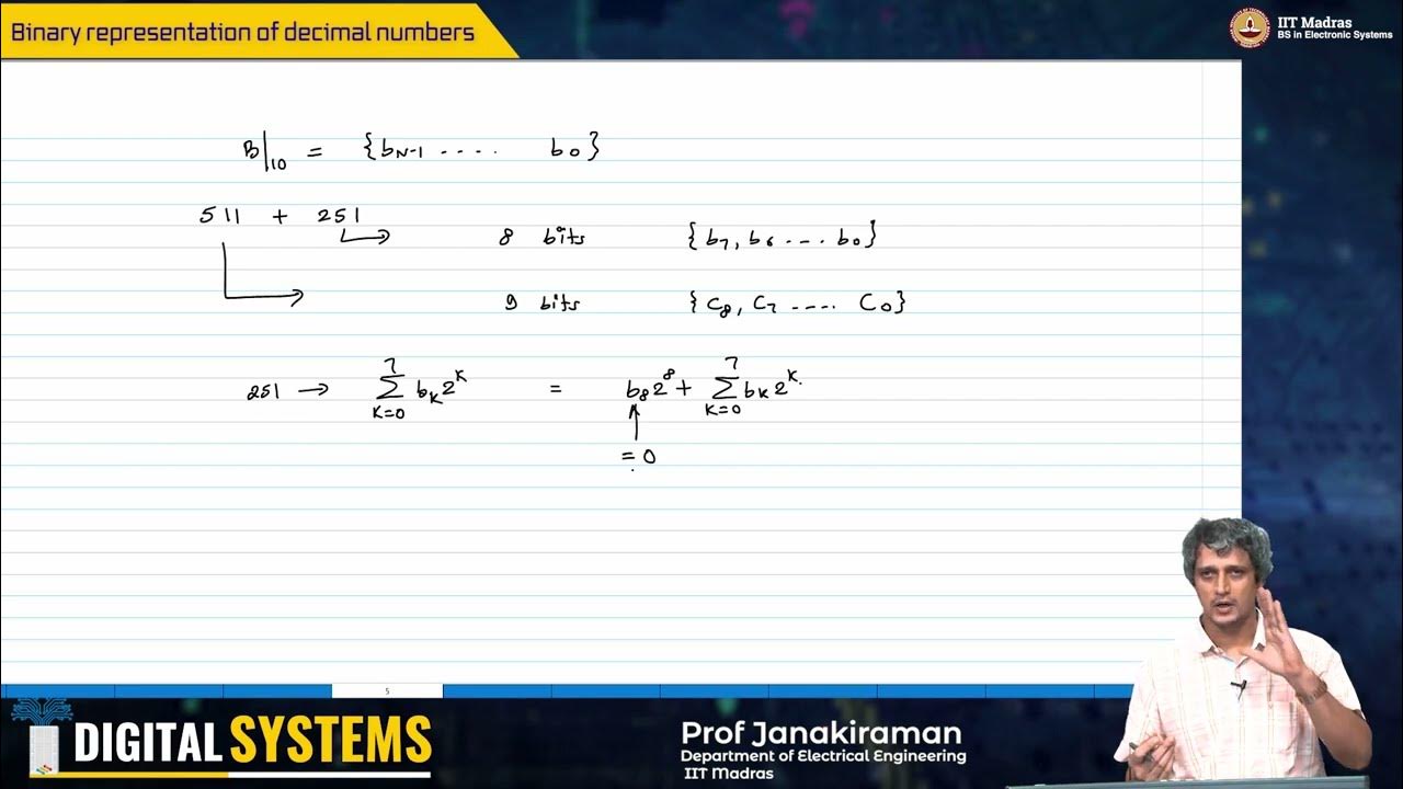
W2_L2_Binary representation of decimal numbers

8.2 Searching in Arrays | Linear and Binary Search | C++ Placement Course |
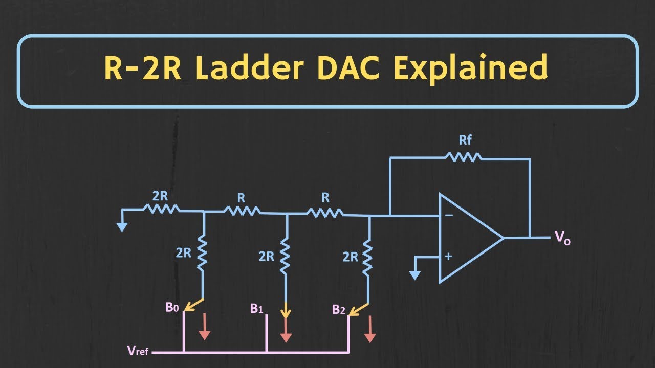
R-2R Ladder DAC Explained (with Solved Example)

Apa Itu Binary Code?

105. OCR A Level (H446) SLR15 - 1.4 Half & full adders

15. OCR GCSE (J277) 1.2 Converting between denary & 8 bit binary
5.0 / 5 (0 votes)
