Praktikum Fisika Dasar - Modul 1 - Rangkaian Hambatan Paralel
Summary
TLDRThis video demonstrates a step-by-step guide on conducting an experiment with a parallel resistor circuit. The process involves setting up the kit, measuring current and voltage across different resistors (R1 and R2), and adjusting the power supply for various voltages. Key tools used include analog and digital multimeters, ammeters, and a power supply. The procedure includes detailed instructions on wiring, adjusting settings, and taking measurements for different conditions, such as 3V, 5V, and 10V, while ensuring safety by powering off devices at each step. The video concludes with tidying up and resetting the equipment after the experiment.
Takeaways
- 😀 Prepare the necessary equipment for the parallel resistor circuit experiment, including the experiment kit, jumper wires, measuring instruments (analog and digital), and power supply.
- 😀 To measure current, use an ammeter and set the selector to the maximum range to ensure accurate readings. Attach the red probe to the positive terminal and the black probe to the negative terminal.
- 😀 Use a digital multimeter to measure voltage. Set it to DC voltage mode and ensure the range is set to auto for accurate results.
- 😀 Before powering the circuit, make sure the power supply is connected to the negative and positive terminals of the circuit.
- 😀 Set the power supply to the desired voltage (e.g., 3V), and adjust the current limit (e.g., 2A) before turning the power on.
- 😀 After setting up the circuit and turning on the power supply, observe the current and voltage readings on the ammeter and multimeter.
- 😀 To measure I2, move the jumper wire accordingly and use the ammeter to observe the new current path.
- 😀 To measure the voltage on R2, place the digital multimeter probes at the correct points and read the voltage value.
- 😀 After each measurement, turn off the power supply and disconnect the measuring instruments to ensure safety and proper handling of the equipment.
- 😀 Repeat the process by changing the power supply voltage to different values (e.g., 5V and 10V) and record the new current and voltage measurements.
- 😀 Once the experiment is complete, turn off the power supply, disconnect all instruments, remove jumper wires, and return the equipment to its original state.
Q & A
What are the main tools required for the parallel resistor circuit experiment?
-The main tools required are the experiment kit, jumper cables, analog and digital multimeters, and a power supply.
How do you measure current in the circuit?
-To measure current, use an ammeter, set it to an appropriate range, and connect the probes: the red probe to the positive side and the black probe to the negative side of the circuit.
Why is it important to set the multimeter to DC when measuring voltage?
-It's important to set the multimeter to DC because the power supply in this experiment is providing DC voltage, and using the correct setting ensures accurate voltage readings.
How do you measure voltage across R1?
-To measure voltage across R1, set the multimeter to DC voltage, select auto range, and connect the red and black probes across R1.
What is the purpose of the jumper cables in this experiment?
-The jumper cables are used to bridge connections and allow the measurement of current (I1 and I2) at different points in the parallel circuit.
How do you measure the total current (I_total) and total voltage (V_total)?
-To measure I_total, move the jumper to the appropriate position and use the analog multimeter to measure current. To measure V_total, use the digital multimeter, ensuring the probes are placed across the entire circuit.
Why do you start with the power supply set to 3V?
-Starting with 3V ensures that the circuit operates within safe limits, preventing any potential damage to the components during the initial testing phase.
What does changing the power supply voltage to 5V and 10V demonstrate?
-Changing the power supply voltage to 5V and 10V allows you to observe how the current and voltage behave when the supply voltage is increased, which helps understand the relationship between voltage and current in a parallel circuit.
What should you do after completing all measurements in the experiment?
-After completing all measurements, turn off the power supply, disconnect all measurement tools, and clean up the experiment setup by removing jumpers and resetting all equipment to its original state.
What is the importance of using both an analog and a digital multimeter in this experiment?
-Using both an analog and a digital multimeter allows for precise measurements of both current and voltage at different points in the circuit, ensuring accurate data for analysis.
Outlines

Esta sección está disponible solo para usuarios con suscripción. Por favor, mejora tu plan para acceder a esta parte.
Mejorar ahoraMindmap

Esta sección está disponible solo para usuarios con suscripción. Por favor, mejora tu plan para acceder a esta parte.
Mejorar ahoraKeywords

Esta sección está disponible solo para usuarios con suscripción. Por favor, mejora tu plan para acceder a esta parte.
Mejorar ahoraHighlights

Esta sección está disponible solo para usuarios con suscripción. Por favor, mejora tu plan para acceder a esta parte.
Mejorar ahoraTranscripts

Esta sección está disponible solo para usuarios con suscripción. Por favor, mejora tu plan para acceder a esta parte.
Mejorar ahoraVer Más Videos Relacionados

HOW TO CONNECT OHM'S LAW CIRCUIT IN 4 MINS | BOARD PRACTICAL | ELECTRICITY DEMO | STD 10-12 PHYSICS
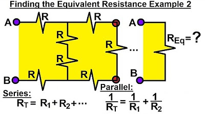
Electrical Engineering: Basic Laws (17 of 31) Finding the Equivalent Resistor Ex. 2
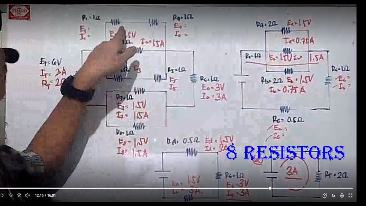
Simple Combination Circuit with 8 resistors

Electrical Engineering: Basic Laws (16 of 31) NOTE ERROR! Finding the Equivalent Resistor Ex. 1
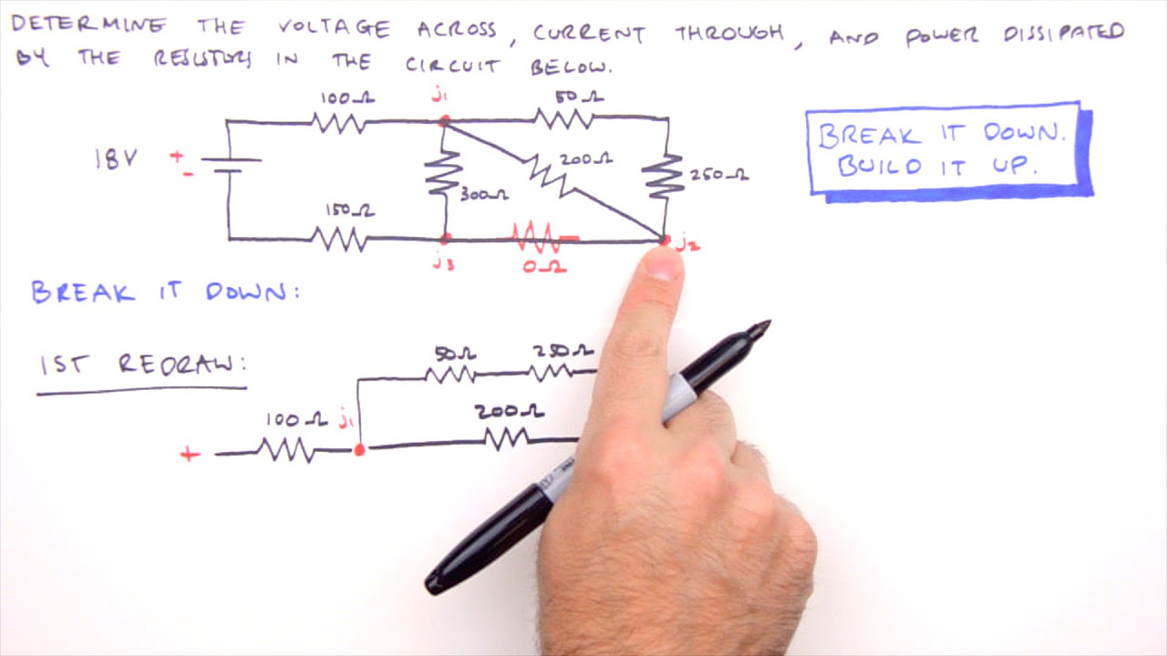
How to Solve Any Series and Parallel Circuit Problem

Superposition Examples (Circuits for Beginners #14)
5.0 / 5 (0 votes)
