How to Solve Any Series and Parallel Circuit Problem
Summary
TLDRIn this educational video, Jesse Mason guides viewers through the analysis of a complex resistive circuit, combining series and parallel resistor configurations. Utilizing the principle of equivalent resistance and Ohm's Law, the tutorial simplifies the circuit step-by-step, calculating voltage, current, and power dissipation across each resistor. The 'Break it down-Build it up' method is introduced, making circuit analysis accessible for beginners and a valuable resource for those tackling physics problems.
Takeaways
- 👋 Introduction by Jesse Mason to analyze a combination resistive circuit.
- 🛠️ The combination circuit includes resistors in both series and parallel configurations.
- 📏 Using principles of equivalent resistance and Ohm's Law to analyze the circuit.
- 🔄 First step is to draw the circuit and label the positive and negative sides of the battery and the junctions.
- 🔧 Replacing an empty leg with a dummy resistor for simpler analysis.
- 🔍 'Break it down-Build it up' method: breaking the circuit down to determine equivalent resistances, then building it back up using Ohm's Law.
- 📉 Redrawing the circuit to make series and parallel relationships more apparent.
- 💡 Calculating equivalent resistance for series resistors by summing their resistances and for parallel resistors using the reciprocal sum method.
- 🔄 Step-by-step redraws and recalculations to simplify the circuit until a single equivalent resistance is found.
- 📊 Building the circuit back up to determine voltage and current for each resistor and calculating power dissipation.
- 📋 Generating a solutions table with voltage, current, and power dissipation for each resistor.
- 🙋 Jesse Mason invites viewers to suggest future topics and engage in the comments.
Q & A
What is the main topic of the video?
-The main topic of the video is the analysis of a combination resistive circuit, which includes resistors in both series and parallel configurations.
Who is the presenter of the Teach Me video?
-Jesse Mason is the presenter of the Teach Me video.
What method does Jesse Mason recommend for analyzing combination circuits?
-Jesse Mason recommends the 'Break it down-Build it up' method for analyzing combination circuits.
What is the purpose of a dummy resistor in circuit analysis as described in the video?
-A dummy resistor, which is a zero-ohm placeholder, is used to simplify the analysis of a circuit, especially for beginners.
How does the video suggest to start the circuit analysis process?
-The video suggests starting the circuit analysis process by drawing and labeling the circuit diagram, including the positive and negative sides of the battery and the junctions.
What is the formula used to calculate the equivalent resistance of resistors in series?
-The formula used to calculate the equivalent resistance of resistors in series is to sum their individual resistances.
How is the equivalent resistance of resistors in parallel calculated according to the video?
-The equivalent resistance of resistors in parallel is calculated as the reciprocal of the sum of the reciprocals of their individual resistances.
What is the role of Ohm's Law in the circuit analysis process demonstrated in the video?
-Ohm's Law is used to determine the voltage across and current through each resistor in the circuit after the equivalent resistance has been calculated.
How does the video describe the process of 'building up' the circuit after determining the equivalent resistance?
-The video describes the process of 'building up' the circuit by moving through the series of redraws in retrograde, determining the values for voltage across and current through each resistor as you go.
What is the final step in the circuit analysis process as shown in the video?
-The final step in the circuit analysis process is to generate a solutions table and calculate the power dissipation for each resistor using the determined voltages and currents.
How does the video suggest determining the current through resistors in parallel?
-The video suggests determining the current through resistors in parallel by using Ohm's Law after establishing that they have the same voltage drop across them.
What is the significance of the current I-0 in the video?
-The current I-0 is significant as it represents the current leaving and re-entering the battery, which is determined using Ohm's Law and the equivalent resistance of the circuit.
How does the video explain the concept of power dissipation in resistors?
-The video explains the concept of power dissipation in resistors as the product of the current through the resistor and the voltage across it.
Outlines

This section is available to paid users only. Please upgrade to access this part.
Upgrade NowMindmap

This section is available to paid users only. Please upgrade to access this part.
Upgrade NowKeywords

This section is available to paid users only. Please upgrade to access this part.
Upgrade NowHighlights

This section is available to paid users only. Please upgrade to access this part.
Upgrade NowTranscripts

This section is available to paid users only. Please upgrade to access this part.
Upgrade NowBrowse More Related Video

Chapter 3 Summary - Simple Resistive Circuits
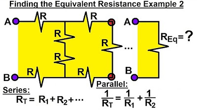
Electrical Engineering: Basic Laws (17 of 31) Finding the Equivalent Resistor Ex. 2
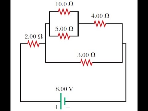
Equivalent Resistance of a Complex Circuit with Series and Parallel Resistors

Electrical Engineering: Basic Laws (16 of 31) NOTE ERROR! Finding the Equivalent Resistor Ex. 1
Consider the circuit shown in the figure below
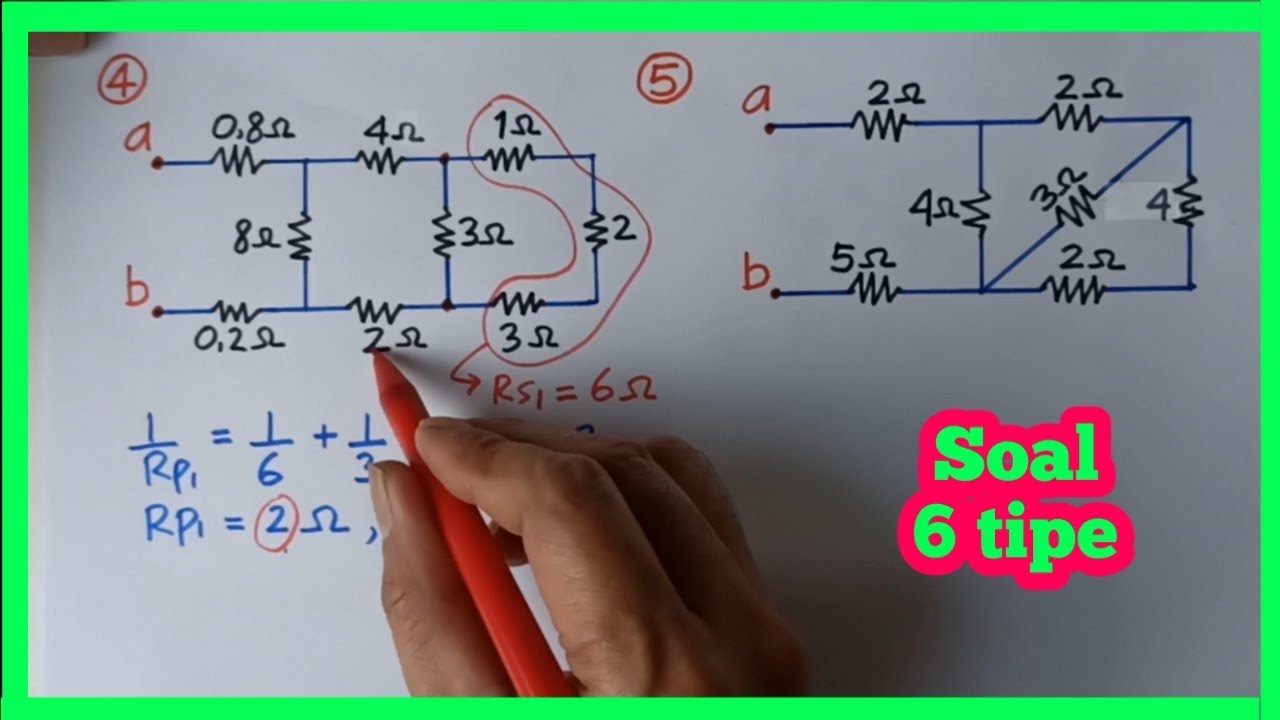
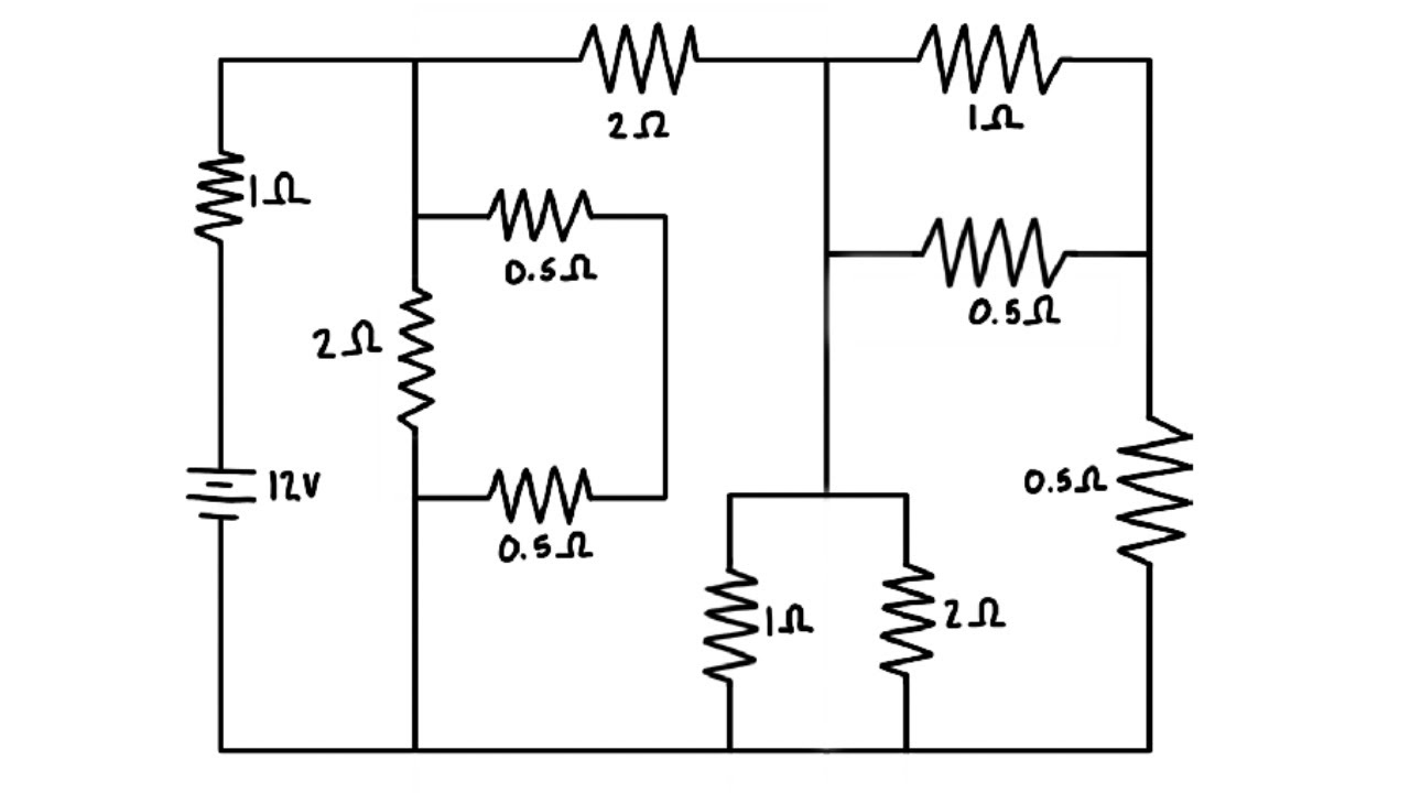
Menghitung Hambatan total / pengganti rangkaian listrik seri paralel majemuk
5.0 / 5 (0 votes)