Homemade Tool Using a Cell Phone Charger with Which You Can Measure Any Electronic Component.
Summary
TLDRIn this video, Professor Nelson demonstrates how to modify a standard cell phone charger to output higher voltages, offering a practical tool for electronics enthusiasts. By replacing the programmable TL431 zener diode with regular zener diodes, and making capacitor adjustments, viewers learn to boost the output to 25V or more. The process includes testing with a voltmeter and measuring components like LEDs and zener diodes. This hands-on project showcases a clever way to enhance chargers for specialized tasks, proving useful for repairing electronics or measuring components beyond a typical multimeter's capabilities.
Takeaways
- 😀 The video demonstrates how to modify a cell phone charger to create a more versatile tool for electronics work.
- 😀 The charger modification involves replacing a programmable zener diode (TL431) with a regular zener diode to adjust the output voltage.
- 😀 Zener diodes can be used to set the output voltage of the modified charger, such as 5V, 10V, 15V, or even higher (up to 25V).
- 😀 The TL431 is a programmable zener diode, used to control the output voltage by activating an LED and transistor in the circuit.
- 😀 By replacing the TL431 with a standard zener diode, the charger can output different voltages based on the zener diode's rating.
- 😀 For higher voltages (e.g., 25V or 27V), additional modifications are required, such as replacing capacitors and ensuring the shocky diode can handle the new voltage.
- 😀 Capacitors on the charger’s board need to be upgraded to handle higher voltages (at least 30V) when increasing the output voltage.
- 😀 The modified charger can deliver more voltage than a standard multimeter, making it a useful tool for measuring and testing components.
- 😀 The charger can be used with a voltmeter to measure voltages across different components, such as LEDs and zener diodes, making it useful for troubleshooting.
- 😀 Proper handling of the voltmeter’s power supply (under 30V) is crucial to avoid damage and ensure accurate measurements of components like LEDs and zener diodes.
Q & A
What is the main objective of the project in the video?
-The main objective of the project is to modify a cell phone charger to create a versatile tool that can measure various voltages, which a regular multimeter cannot do.
What is the role of the TL431 diode in the charger circuit?
-The TL431 is a programmable zener diode that helps regulate the output voltage by activating when the voltage reaches a specific programmed value, controlling the flow of current and stopping the voltage from increasing further.
Why is the TL431 diode replaced with a regular zener diode?
-The TL431 is replaced with a regular zener diode to modify the charger’s output voltage, enabling the charger to supply a different voltage than originally programmed, such as 6V, 25V, or even higher.
How do you calculate the output voltage after replacing the TL431 diode?
-The output voltage is the sum of the voltage determined by the zener diode and the voltage from the LED. For example, if the zener diode is 5V and the LED adds 1V, the total output voltage would be 6V.
Why is it important to use capacitors with a voltage rating higher than the modified output?
-It is important because the capacitors need to handle the increased voltage without failing. For example, when modifying the charger to deliver 25V, capacitors with a rating of at least 30V or higher are required.
What is the role of the SR5100 shocky diode in the charger modification?
-The SR5100 shocky diode is responsible for protecting the circuit from overvoltage. It can handle up to 100V, but if the charger is modified to output more than its rated capacity, the diode may need to be replaced with one that supports a higher voltage.
Why is the modification of the charger limited to 25V and not higher?
-The modification is limited to 25V because the voltmeter used in the tool is rated to operate safely at voltages below 30V. Going beyond this could damage the voltmeter and other components.
How does the voltmeter measure the voltage of components?
-The voltmeter is connected to the charger’s output, with the green wire leading to the component to be measured. A resistor (4.7 kΩ) is placed in series to limit current, allowing the voltmeter to display the voltage across the component.
What type of diodes can be measured using the modified charger tool?
-The modified charger tool can be used to measure zener diodes in reverse polarity, as well as regular diodes, by checking the voltage drop across them. It can also be used to test the voltage drops in LEDs and assess their functionality.
Why is it necessary to measure zener diodes in reverse polarity?
-Zener diodes must be measured in reverse polarity because they are designed to conduct in reverse when the breakdown voltage is reached. Measuring them in the forward direction would show a typical diode voltage drop of about 0.7V.
Outlines

Esta sección está disponible solo para usuarios con suscripción. Por favor, mejora tu plan para acceder a esta parte.
Mejorar ahoraMindmap

Esta sección está disponible solo para usuarios con suscripción. Por favor, mejora tu plan para acceder a esta parte.
Mejorar ahoraKeywords

Esta sección está disponible solo para usuarios con suscripción. Por favor, mejora tu plan para acceder a esta parte.
Mejorar ahoraHighlights

Esta sección está disponible solo para usuarios con suscripción. Por favor, mejora tu plan para acceder a esta parte.
Mejorar ahoraTranscripts

Esta sección está disponible solo para usuarios con suscripción. Por favor, mejora tu plan para acceder a esta parte.
Mejorar ahoraVer Más Videos Relacionados

Diode Solved Problems | Quiz # 110 and Quiz # 114

How to make Solar smartphone charger
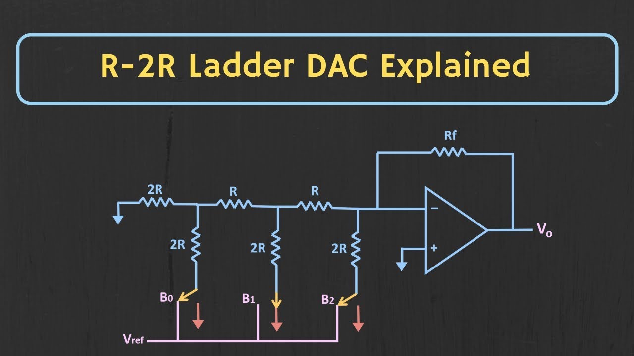
R-2R Ladder DAC Explained (with Solved Example)

LiitoKala Lii-S12, 12 slot smart battery charger Li-ion, IMR, LifePo4, Nimh, Nicd, AA, AAA, 18650
CARA MENGGUNAKAN MULTITESTER ANALOG BAGI PEMULA

Qi vs Qi2 vs MagSafe - Ultimate Wireless Charging Test!
5.0 / 5 (0 votes)
