Operation of Power Electronics Boost Converters - How to Calculate the Output Voltage
Summary
TLDRIn this lecture, the workings of a boost converter are explained, highlighting its ability to step up the voltage. The process includes analyzing the circuit and switching transistor Q1 between two states, where it is on and off at specific intervals, affecting the behavior of the inductor and diode. The voltage across the inductor and the output voltage relationship are derived using Kirchhoff’s voltage law, revealing the converter’s output voltage as a function of the input voltage and duty ratio. Practical examples illustrate how adjusting the duty ratio (d) alters the output voltage, demonstrating the boost converter's function in stepping up the voltage.
Takeaways
- 😀 The boost converter steps up the input voltage, providing a higher output voltage.
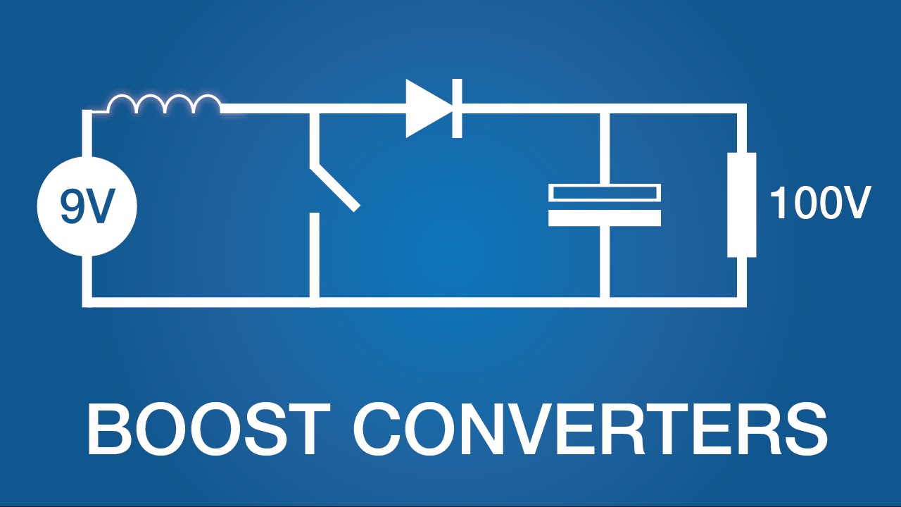
- 😀 The key components of the boost converter are an inductor, capacitor, diode, transistor, and load.
- 😀 The transistor (Q1) switches on and off during one cycle, with a duty cycle determining how long it stays on.
- 😀 During the first state, when the transistor is on, the inductor stores energy and the diode is off.
- 😀 During the second state, when the transistor is off, the inductor releases its energy through the diode to the load.
- 😀 The voltage across the inductor is equal to the input voltage (V_n) in state 1 and to (V_n - V_out) in state 2.
- 😀 The energy stored and released in the inductor must balance to maintain steady-state operation.
- 😀 The relationship between the output and input voltage is given by the equation: V_out = V_n / (1 - d), where d is the duty cycle.
- 😀 A higher duty cycle (d close to 1) results in a much higher output voltage compared to the input.
- 😀 Practical duty cycles range from 0.1 to 0.9, where a duty cycle of 0.1 gives a voltage boost of about 1.11 times, and a duty cycle of 0.9 gives a voltage boost of 10 times.
- 😀 The boost converter operates in steady-state as long as the energy being stored in the inductor is equal to the energy being released in each cycle.
Q & A
What is the main function of a boost converter?
-The main function of a boost converter is to step up the input voltage, meaning the output voltage will have a greater magnitude than the input voltage.
What components are included in the boost converter circuit?
-The boost converter circuit includes an inductor, a capacitor, an output load, a diode, and a transistor.
How is the transistor (Q1) controlled in a boost converter?
-The transistor Q1 is switched on from 0 to π and switched off from π to 2π, creating a control signal with a duty ratio of 0.5, meaning it is on for half the period.
What happens during the first state (0 to π) when Q1 is on?
-During the first state, when Q1 is on, the circuit is formed by the input voltage (Vn), the inductor (L1), the transistor (Q1), and the input voltage again, with the voltage across the inductor (VL1) equal to Vn.
What occurs when Q1 is turned off in the second state (π to 2π)?
-When Q1 is turned off, the energy stored in the inductor (L1) flows through the diode (D1) and the output load. The voltage loop equation for this state is adjusted to show the voltage across the inductor (VL1) is equal to Vn minus Vout.
Why is steady state important in a boost converter?
-Steady state is important because it ensures that the energy stored in the inductor during the first state is equal to the energy discharged from the inductor during the second state, maintaining a stable operation where the average energy over one period is zero.
How do we calculate the relationship between output and input voltage in a boost converter?
-The relationship between the output voltage (Vout) and input voltage (Vn) is given by the formula Vout = Vn / (1 - d), where d is the duty ratio. This shows that Vout is greater than Vn as long as d is not zero.
What is the significance of the duty ratio (d) in the boost converter's voltage conversion?
-The duty ratio (d) directly influences the output voltage. As d increases, the output voltage becomes significantly larger than the input voltage. For example, when d is 0.9, the output voltage can be 10 times the input voltage.
What would happen if the duty ratio (d) were very close to 1?
-If the duty ratio (d) were very close to 1, the output voltage (Vout) would become very large, as the denominator of the formula (1 - d) would approach zero, resulting in a large value for Vout.
Can the boost converter's output voltage ever be equal to the input voltage?
-Yes, if the duty ratio (d) is zero, the output voltage will be equal to the input voltage, as the formula for Vout shows that when d is zero, Vout equals Vn.
Outlines

Esta sección está disponible solo para usuarios con suscripción. Por favor, mejora tu plan para acceder a esta parte.
Mejorar ahoraMindmap

Esta sección está disponible solo para usuarios con suscripción. Por favor, mejora tu plan para acceder a esta parte.
Mejorar ahoraKeywords

Esta sección está disponible solo para usuarios con suscripción. Por favor, mejora tu plan para acceder a esta parte.
Mejorar ahoraHighlights

Esta sección está disponible solo para usuarios con suscripción. Por favor, mejora tu plan para acceder a esta parte.
Mejorar ahoraTranscripts

Esta sección está disponible solo para usuarios con suscripción. Por favor, mejora tu plan para acceder a esta parte.
Mejorar ahoraVer Más Videos Relacionados


5.0 / 5 (0 votes)
