Boost Your RC Circuit Analysis Skills with an Oscilloscope Lab
Summary
TLDRThis hands-on experiment demonstrates the setup and analysis of an RC circuit using a function generator and oscilloscope. The goal is to measure the capacitor's charging and discharging behavior, adjusting the oscilloscope's settings to capture accurate waveforms. Key measurements such as voltage, frequency, and time constants are collected, with a focus on understanding the capacitor's response in the circuit. After capturing initial data with a known capacitor, the experiment is repeated with an unknown capacitor to calculate its time constant. The process emphasizes practical lab skills and the application of electrical theory to real-world scenarios.
Takeaways
- 😀 Adjusting the output level to approximately 2500 and fine-tuning the settings on the oscilloscope for accuracy.
- 😀 Setting the range to 5000 allows for the use of both coarse and fine knobs to fine-tune the frequency to 2500 Hz.
- 😀 Using the auto set function on the oscilloscope to calibrate the display and achieve a clearer waveform representation.
- 😀 The oscilloscope's vertical scale of 20 volts per square and horizontal scale of 200 microseconds per square helps in measuring voltage and time precisely.
- 😀 The goal is to ensure the waveform is exactly tuned to 10,000 Hz, requiring careful adjustments to the oscilloscope's settings.
- 😀 Zooming in on the oscilloscope display allows for a better view of three full cycles, with a voltage reading of 12.1 V.
- 😀 The frequency and voltage are adjusted until three full cycles fit neatly in the oscilloscope’s display window.
- 😀 The cursor button is used to measure the amplitude, helping to fine-tune voltage measurements for accuracy.
- 😀 The final waveform's peak-to-peak voltage is approximately 119 V, with each square on the oscilloscope representing 20.4 V.
- 😀 A decade resistor box is used to set the resistance to 2,950 Ω, which is part of setting up a circuit for waveform generation and measurement.
- 😀 The capacitor charges and discharges in cycles, with distinct flat lines on the oscilloscope representing periods where the capacitor is fully charged or discharged.
Q & A
What is the purpose of adjusting the output level to about halfway in the experiment?
-The purpose of adjusting the output level is to ensure that the signal generated by the function generator is at an appropriate amplitude for the experiment. The specific setting of 2500 helps in fine-tuning the signal for accurate measurement and analysis.
Why is the range set to about 5000 on the equipment?
-The range is set to 5000 to allow the course and fine knobs to be used effectively for precise tuning. This helps in adjusting the signal accurately within the desired frequency range.
What does the 'auto set' button do on the oscilloscope?
-The 'auto set' button on the oscilloscope automatically adjusts the settings to provide a clear and stable waveform display. It helps ensure that the signal is properly aligned and ready for further analysis.
How is the time and voltage scale set on the oscilloscope for accurate measurements?
-The time and voltage scales are adjusted by zooming in on the signal, ensuring that the waveform fits neatly within the screen. This allows for more accurate measurement of the cycles, voltage, and time periods.
What is the significance of the flat areas on the waveform during charging and discharging of the capacitor?
-The flat areas on the waveform indicate the periods when the capacitor is fully charged or discharged. These flat lines are important as they mark the points where there is no further voltage change, helping in the analysis of the charging and discharging process.
How is the voltage measured across the capacitor during the experiment?
-The voltage across the capacitor is measured using the oscilloscope probe. The probe is connected to the capacitor, and the oscilloscope displays the voltage changes as the capacitor charges and discharges over time.
What does the delta V represent in the experiment?
-The delta V represents the difference in voltage between two points on the waveform. It is used to quantify the voltage change across the capacitor as it charges or discharges.
What role does the resistor play in the circuit setup?
-The resistor in the circuit helps control the charging and discharging rate of the capacitor. It ensures that the capacitor charges at a specific rate and allows for the measurement of voltage changes across the capacitor.
What is the significance of the 'cursor' button on the oscilloscope?
-The 'cursor' button on the oscilloscope is used to place markers on the waveform at specific points, allowing for precise measurements of time, voltage, and other parameters. This helps in the analysis of the waveform, especially for tasks like calculating the time constant.
How is the time constant calculated from the data in this experiment?
-The time constant is calculated by taking the natural logarithm of the voltage equation for a capacitor as it discharges. The data points collected from the oscilloscope, such as voltage at different times, are used to generate a curve from which the time constant can be derived.
Outlines

Esta sección está disponible solo para usuarios con suscripción. Por favor, mejora tu plan para acceder a esta parte.
Mejorar ahoraMindmap

Esta sección está disponible solo para usuarios con suscripción. Por favor, mejora tu plan para acceder a esta parte.
Mejorar ahoraKeywords

Esta sección está disponible solo para usuarios con suscripción. Por favor, mejora tu plan para acceder a esta parte.
Mejorar ahoraHighlights

Esta sección está disponible solo para usuarios con suscripción. Por favor, mejora tu plan para acceder a esta parte.
Mejorar ahoraTranscripts

Esta sección está disponible solo para usuarios con suscripción. Por favor, mejora tu plan para acceder a esta parte.
Mejorar ahora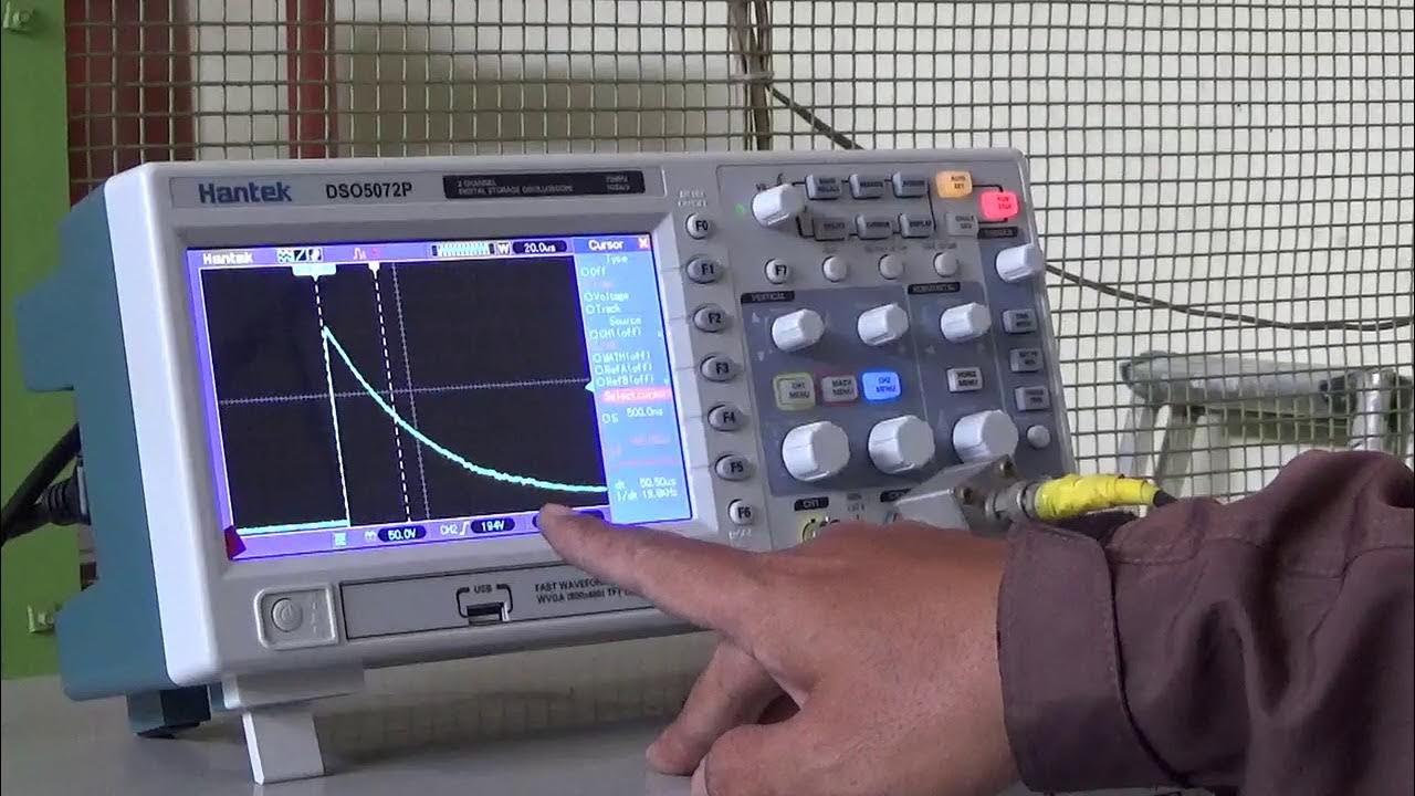


5.0 / 5 (0 votes)
