Using Diodes as Clippers or Clampers | Intermediate Electronics

CircuitBread
23 Jun 202009:45

Summary

TLDRIn this educational video, the presenter explores the concepts of clippers and clampers in electronics, using a simple circuit setup with a waveform generator and oscilloscope. They demonstrate various types of clippers, including negative and positive series clippers, and how they clip the input signal differently. The video also covers biased series clippers and their behavior with DC offsets. Parallel clippers are shown, highlighting the diode's role in determining the load voltage. Finally, a clamper circuit is explained, illustrating how it shifts the entire waveform's voltage. The presenter encourages hands-on learning and refers viewers to a detailed written tutorial by Harold for further understanding.

Takeaways

  • πŸ”¬ The tutorial focuses on demonstrating clippers and clampers in electronic circuits.
  • πŸ“š Harold's written tutorial on CircaBred.com is recommended for detailed mathematical explanations.
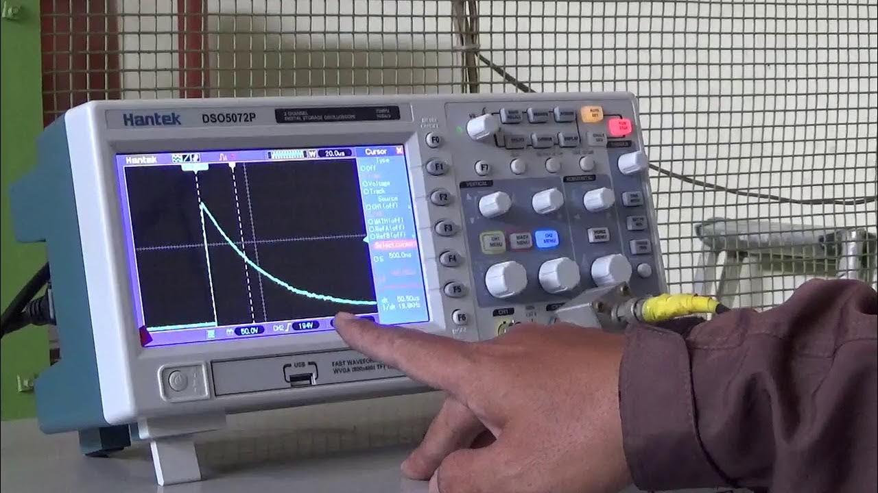
  • πŸ”Œ The setup includes a simple circuit connected to a waveform generator and an oscilloscope.
  • πŸ“ˆ The oscilloscope displays the output of the generator and the effect across the load with different circuits.
  • ⚑ A negative series clipper is shown first, which clips the positive part of the input signal, similar to a half-wave rectifier.
  • πŸ”„ Flipping the diode demonstrates a positive series clipper, which clips the negative part of the input signal.
  • πŸ”Œ Biased series clippers are shown with a DC offset, affecting the clipping level of the input signal.
  • πŸ”— Parallel clippers are introduced, where the diode is in parallel with the load, affecting the voltage across the load based on diode bias.
  • πŸ”‹ A clamper circuit is demonstrated, which uses a capacitor and a diode to shift the entire waveform up or down in voltage.
  • πŸŽ₯ The video emphasizes the importance of hands-on experience and practical demonstration for better understanding of these concepts.

Q & A

  • What is the main topic of the tutorial video?

    -The main topic of the tutorial video is about clippers and clampers in electronic circuits.

  • Who created the written tutorial mentioned in the video?

    -Harold created the written tutorial on clippers and clampers.

  • What is the purpose of using a waveform generator and an oscilloscope in the demonstration?

    -The purpose of using a waveform generator and an oscilloscope is to show the output of the generator and what happens across the load with different circuits.

  • What is a negative series clipper and how is it demonstrated in the video?

    -A negative series clipper is a circuit that clips the positive part of an input signal, leaving only the negative part. It is demonstrated by showing the output on an oscilloscope after the signal passes through a diode.

  • How does a positive series clipper differ from a negative series clipper?

    -A positive series clipper is set up by reversing the diode in the circuit, which results in clipping the negative part of the input signal, leaving only the positive part.

  • What is the effect of bias on a series clipper circuit?

    -Biasing a series clipper circuit shifts the entire waveform up or down. A positive bias shifts the waveform up, clipping less of the negative part, while a negative bias shifts it down, clipping less of the positive part.

  • What is the role of the diode in a parallel clipper circuit?

    -In a parallel clipper circuit, the diode allows current to flow through the load only when it is reverse-biased, effectively clipping the signal when the diode is forward-biased.

  • How does the bias affect the output of a parallel clipper?

    -Biasing a parallel clipper affects the output by shifting the point at which the diode starts to conduct. A positive bias reduces the voltage across the load during forward bias, while a negative bias increases it.

  • What is a clamper circuit and how does it differ from a clipper?

    -A clamper circuit is designed to shift the entire waveform up or down without clipping it. It differs from a clipper in that it does not remove parts of the waveform but rather shifts the entire waveform to a new voltage level.

  • What components are typically used in a clamper circuit?

    -A clamper circuit typically uses a diode, a capacitor, and a resistor. The capacitor is in series with the diode, and the resistor is in parallel with them.

  • Why does the clamper circuit not provide a free increase in voltage?

    -The clamper circuit does not provide a free increase in voltage because it shifts the entire waveform up or down without adding or removing energy from the circuit; it merely redistributes the existing voltage levels.

Outlines

00:00

πŸ”¬ Introduction to Clippers and Clampers

This paragraph introduces the topic of clippers and clampers in electronics, with a focus on a tutorial created by Harold. The tutorial is available on Circa Bred Calm and is highly recommended for its detailed explanations involving math. The video aims to demonstrate the practical application of the clippers described in the written tutorial. The setup includes a simple circuit connected to a waveform generator and an oscilloscope, which is used to display the output of the generator and the effect across the load with different circuits. The oscilloscope shows two channels, one for the generator's output and another for the load's output. The video begins with a negative series clipper, which clips the incoming signal, demonstrated with a 60 Hertz input at 10 volts. The oscilloscope displays a flatline when the input is turned off, and the clipper is compared to a half-wave rectifier. The video then transitions to a positive series clipper by simply reversing the diode's orientation, resulting in the negative cycle being clipped. The concept of bias is introduced, explaining how an average offset can affect the clipping behavior. The video concludes with a demonstration of a biased negative series clipper, where an offset is applied to the waveform generator, and the resulting shift in the output is observed.

05:01

πŸ”Œ Exploring Parallel Clippers and Clampers

The second paragraph delves into parallel clippers, starting with a setup where the diode is in parallel with the load. The behavior of the circuit is explained in terms of the diode's forward and reverse biasing, affecting the voltage across the load. When the diode is forward biased, there is no voltage across the load, but when reverse biased, the negative dip is observed. The video then demonstrates the effect of biasing the circuit, showing how the clipping behavior changes with a DC offset. The discussion moves on to clampers, where a setup with a capacitor in series with a diode and a resistor in parallel is presented. The oscilloscope is used to observe the waveform's shift due to the capacitor's discharge and the effect of the clamper circuit. The video explains that a clamper shifts the entire waveform up or down without adding or losing voltage, as it's merely a redistribution of the existing voltage. The demonstration concludes with a comparison of the series and parallel configurations of clippers and the clamper, emphasizing the importance of hands-on experience and referring viewers to Harold's more advanced tutorial for further understanding.

Mindmap

Keywords

πŸ’‘Clippers

Clippers are circuits that limit the amplitude of a waveform to a certain level. In the video, the presenter demonstrates how clippers work by using a simple circuit connected to a waveform generator and an oscilloscope. The script mentions 'negative series clipper' and 'positive series clipper,' which refer to the polarity of the clipped portion of the waveform. Clipping is a form of signal processing used in various electronic applications, such as audio and telecommunications.

πŸ’‘Clampers

Clampers are circuits that shift the voltage level of a waveform up or down to a specific reference level. The video script describes a clamper circuit that uses a capacitor, a diode, and a resistor to achieve this. Clampers are used to protect sensitive electronic components from voltage spikes or to ensure that signals stay within a certain voltage range, as illustrated in the script by the demonstration of a clamper shifting the waveform down by a fixed voltage.

πŸ’‘Waveform Generator

A waveform generator is a device that produces specific waveforms, such as sine, square, or triangle waves. In the video, the waveform generator is used to provide a controlled input signal to the circuits being demonstrated. The script mentions setting the generator to produce a 60 Hertz sine wave at 10 volts peak-to-peak, which simulates the typical mains frequency and voltage for testing the clippers and clampers.

πŸ’‘Oscilloscope

An oscilloscope is an electronic test instrument that allows the visualization of waveforms. In the video, the oscilloscope is used to display the output of the waveform generator and the effects of the clippers and clampers on the waveform. The script describes using both channels of the oscilloscope to show the input signal and the modified signal across the load.

πŸ’‘Diode

A diode is a two-terminal electronic component that allows current to flow in one direction and blocks it in the other. In the video, diodes are used in the clipper and clamper circuits to control the flow of current and to clip or clamp the waveform. The script explains how changing the orientation of the diode can switch between a negative and positive series clipper.

πŸ’‘Bias

Bias in electronics refers to a DC offset that is added to a signal. In the video, the presenter demonstrates how biasing affects the operation of clippers by using the waveform generator to apply a DC offset to the input signal. The script describes how this bias shifts the waveform up or down, affecting the clipping point of the clipper circuit.

πŸ’‘Series and Parallel Configuration

These terms refer to the way components are connected in a circuit. In the video, the script explains the difference between series and parallel clippers. In a series clipper, the diode is in series with the load, affecting the voltage across the load directly. In a parallel clipper, the diode is in parallel with the load, and the voltage across the load depends on whether the diode is forward or reverse biased. The video demonstrates both configurations.

πŸ’‘Resistor

A resistor is a passive electronic component that opposes the flow of electric current. In the video, resistors are used in the clipper and clamper circuits to control the current flow and to set the level of clipping or clamping. The script mentions a 100k resistor used in the clamper circuit to measure the voltage across the load.

πŸ’‘Capacitor

A capacitor is a passive electronic component that stores electrical energy in an electric field. In the video, a capacitor is used in the clamper circuit to store charge and to shift the voltage level of the waveform. The script describes how the capacitor, in conjunction with a diode and resistor, creates a voltage shift that clamps the waveform to a specific level.

πŸ’‘RC Discharge

RC discharge refers to the time it takes for a capacitor to discharge through a resistor. In the video, the script mentions the RC discharge in the context of the capacitor in the clamper circuit. As the capacitor discharges, it affects the waveform's shape, creating a curve as the capacitor starts to discharge before the next voltage peak arrives.

Highlights

Introduction to clippers and clampers in electronic circuits

Recommendation of a written tutorial on CircaBred.com for detailed explanations

Demonstration of a simple circuit setup with a waveform generator and oscilloscope

Explanation of negative series clipper and its function in a circuit

Visual representation of a 60 Hertz input signal on an oscilloscope

Comparison of a negative series clipper to a half-wave rectifier

Setup for a positive series clipper by reversing the diode orientation

Observation of the positive series clipper's output on the oscilloscope

Discussion on biased series clippers and the role of DC offset in circuit behavior

Demonstration of how bias affects the clipping level in a circuit

Introduction to parallel clippers and their configuration in a circuit

Comparison between series and parallel clippers in terms of voltage across the load

Setup and explanation of a biased parallel clipper circuit

Transition to clamper circuits and their function in voltage shifting

Demonstration of a clamper circuit with a capacitor, diode, and resistor

Explanation of how a clamper shifts the entire waveform up or down without adding voltage

Practical advice on hands-on experience with electronic circuits

Conclusion and call to action for viewers to engage with the tutorial and experiment

Transcripts

play00:00

[Music]

play00:02

so today we're going to learn about

play00:04

clippers and clampers now Harold put

play00:06

this tutorial together and he did a

play00:07

great job it's a written tutorial on

play00:09

circa bred calm and I highly recommend

play00:10

you go check it out he goes into the

play00:11

details with the math and all that sort

play00:13

of jazz but today on this video I want

play00:16

to show some of those Clippers that he

play00:17

describes in action so here I have a set

play00:20

up with my very very simple circuit and

play00:23

it is hooked up to a waveform generator

play00:25

and an oscilloscope and I'm using both

play00:27

channels of the oscilloscope to show the

play00:29

output of the generator and then also

play00:31

show what happens across the load with

play00:34

these different circuits so there's a

play00:36

whole lot of connections here you've got

play00:37

three grounds here for the two channels

play00:39

on the oscilloscope and one for the

play00:40

waveform generator and then I'm

play00:42

measuring across the load and then I'm

play00:44

measuring across the entire thing and

play00:46

then of course the waveform generator

play00:48

itself is going in so it's kind of funny

play00:50

to me that I only have two components on

play00:51

here and six things hook to them but

play00:53

that's that's how it is so this first

play00:56

thing that we have is what we call a

play00:57

negative series clipper and so this

play01:00

clips the signal that's coming in and so

play01:02

what I have here is a 60 Hertz because

play01:04

that's generally we're dealing with wall

play01:06

frequency if so 50 60 Hertz so I have a

play01:10

60 Hertz input and I can't do 128 volts

play01:13

output on this so I'm just doing 10

play01:15

volts and then I'm showing what it looks

play01:17

like on this so on the oscilloscope

play01:19

you'll see the yellow is what is being

play01:22

measured across the load in the blue is

play01:25

the output from the waveform generator

play01:27

so you can see we have five volts per

play01:28

veted per division so we've got 10 volts

play01:31

up and down there so if I turn off

play01:33

channel 2 or the input you can see very

play01:37

clearly that we just have flatline OOP

play01:41

flatline and if you've looked at any of

play01:44

our other tutorials particularly on the

play01:46

half wave rectifier you'll be like hey

play01:47

that's just a half wave rectifier and

play01:49

you would be right and that is what the

play01:52

first negative series clipper looks like

play01:54

so now to do a positive series clipper

play01:56

all we have to do is switch this diode

play01:58

around and put it in the other direction

play02:00

so let me do that really quick okay so

play02:03

it just set it up all I did was flip the

play02:04

diode around and I hooked everything

play02:06

back up and you can see that my

play02:07

oscilloscopes going crazy and that is

play02:09

because my trigger

play02:10

at the wrong spot now so I need to

play02:12

trigger it down there and so it looks

play02:14

exactly like the positive series clipper

play02:16

but now it's upside down and all we're

play02:18

getting is the negative cycle on the

play02:21

bottom so let's turn that back on so

play02:24

again this is what the input is and

play02:25

that's the output is and you can see

play02:27

there's not going to be an exact overlap

play02:30

one just because I don't have this set

play02:33

up super fantastic but also because

play02:35

there is gonna be the slightest voltage

play02:37

drop across the diode so you can see the

play02:39

input is all the way giving me a nice

play02:41

beautiful sine wave but then my output

play02:44

it's clipping the top off instead of the

play02:46

bottom and so that's what you get with a

play02:47

positive series clipper so now let's go

play02:50

to the next thing which is the biased

play02:52

series clipper so we'll up until this

play02:54

point we've been assuming that the

play02:56

average is zero and so if we were to

play02:58

have an op-amp or something some sort of

play03:00

adder or some sort of DC offset in our

play03:02

circuit we would see a shift so I'm

play03:05

gonna flip this diode back around and

play03:06

I'm going to fake that DC offset with my

play03:10

waveform generator so let's do that

play03:11

really quick okay so now I've flipped

play03:13

the diode back and we are back in a

play03:15

negative series clipper circuit and you

play03:16

can see I haven't done the offset yet so

play03:20

we have our typical output but let me go

play03:23

over here and change the offset and I

play03:25

really hope that you have access to

play03:26

these tools either at school or at work

play03:27

or something like that so you can go

play03:29

over and you can do this exact same

play03:30

thing in your own space and also again

play03:32

Harold has even more advanced Dennis

play03:35

demonstrations of how to do this of more

play03:38

advanced clippers and clampers so if you

play03:41

have access to this I highly recommend

play03:43

hands-on and seeing it for yourself

play03:45

because videos are great but there's

play03:46

nothing like hands-on experience so

play03:48

hopefully you can do that but coming

play03:49

back to this we have our 60 Hertz 10

play03:51

volts peak-to-peak in zero offset right

play03:52

now but now let's start to give myself

play03:55

an offset so I have a two bowl offset

play03:58

three volt and as you see everything is

play04:01

getting shifted up and so is this so

play04:04

you're still getting that beautiful sine

play04:05

wave and it's just clipping it lower and

play04:07

lower at that zero point so let me go up

play04:11

a little bit more if you bias it enough

play04:14

which that's the max for my arbitrary

play04:16

waveform generator you can see it's

play04:18

almost a perfect sine wave but

play04:20

completely above the zero point and then

play04:22

if we bias it in the

play04:24

direction and get a negative voltage

play04:26

then even less comes up and now we're

play04:28

getting below the trigger points so it's

play04:30

not even detecting it but it's just

play04:31

getting smaller and smaller until

play04:32

there's nothing left because at negative

play04:35

five volt DC with a 10 volt peak-to-peak

play04:38

the very peak of this sine wave is at

play04:40

zero so of course you're not going to

play04:42

see it so those are our positive and our

play04:45

negative

play04:46

series Clippers with and without bias

play04:49

now let's move to parallel Clippers okay

play04:51

so our first parallel clipper is set up

play04:54

now and really the biggest thing you can

play04:56

notice here is that the diode is in

play04:58

parallel with the load so if there's a

play05:00

voltage across the diode there's gonna

play05:02

be a voltage across the load if there's

play05:03

not a voltage across the diode there's

play05:05

not going to be a voltage across the

play05:06

load so in this one I have the cathode

play05:08

hooked up to ground and so when it is

play05:10

being forward biased there is basically

play05:13

no there there's a point seven volt drop

play05:16

in and if we assume diode is ideal there

play05:19

is no voltage across that so if there's

play05:20

no voltage across the diode then there's

play05:22

gonna be no voltage across the load so

play05:25

we come over here and I need to set my

play05:27

trigger down here again but we can see

play05:29

that this is when it is forward bias

play05:31

because there there's no voltage across

play05:34

this diode but when it's being reverse

play05:36

biased that is when you get that

play05:38

negative dip so let's switch this around

play05:40

and you can take a brief second wand

play05:41

switching this to think of what exactly

play05:43

you think this is going to look like

play05:44

when it's in the parallel configuration

play05:46

when the cathode is on the positive side

play05:51

okay now as I'm sure you figure it out

play05:54

we're basically seeing the other side we

play05:57

just inverted it and this is one of

play05:58

those things if you're doing it in

play05:59

series or in parallel the way you have

play06:01

the diode it kind of flips your

play06:06

understanding because now instead of

play06:08

measuring the voltage on the other side

play06:10

of the diode you're measuring the

play06:11

voltage across the diode and so

play06:13

depending on what you need to do

play06:15

depending on what you want to do you can

play06:17

either do the series or parallel

play06:19

configuration for a clipper circuit now

play06:23

let's just bias this really quick there

play06:24

shouldn't be any surprises here either

play06:26

and then we'll go on to our clamper

play06:28

example so make sure I'm on my offset

play06:30

yep

play06:31

so acts just like you would expect with

play06:34

the other one with the series

play06:38

so as you bias it up you're gonna see

play06:40

more it's gonna still retain that shape

play06:43

of the sine wave is just gonna clip off

play06:45

certain sections clipper clip it off

play06:48

yeah that's where we're going with that

play06:50

and then if I reverse bias it it's just

play06:52

going to go away and the interesting

play06:55

thing is if you notice earlier with the

play06:57

series we weren't able to get the very

play06:59

bottom tip of this whereas we were able

play07:02

to completely hide it whereas you can

play07:06

still see little divots here so that is

play07:08

because we are putting that seven point

play07:10

seven volt drop somewhere else in the

play07:13

circuit and so you see a little bit of a

play07:15

shift there okay so let's put together

play07:17

the climber alright so I just finally

play07:19

set it up as they clamp er and as you

play07:22

can see you have a capacitor that is in

play07:24

series with a diode and a resistor that

play07:26

are in parallel and that's something you

play07:28

can see on the schematic and I again I'm

play07:30

measuring over the resistor and as the

play07:32

load and also the over the entire thing

play07:35

so let's look at the oscilloscope here I

play07:37

have it 10 volts peak to peak at about a

play07:39

thousand Hertz I had to change out the

play07:41

value of my resistor is a 100k resistor

play07:43

and a now I have a point 1 there at

play07:45

micro farad capacitor in here and so as

play07:49

we look at the original what's coming in

play07:53

let me get that you can see that being a

play07:56

10 volt peak-to-peak peak to peak you

play07:58

get a 5 volt jump and then the negative

play08:00

5 volts +5 volts negative 5 volts now as

play08:03

we turn the output back on basically

play08:08

what we're getting is we're getting 0

play08:10

volts negative 10 volts 0 volts negative

play08:12

10 volts so we're shifting that peak

play08:15

basically just taking our entire

play08:17

waveform and shifting it down 5 volts

play08:20

and so it's an interesting thing because

play08:22

we're not in gaining anything here it's

play08:23

not like we're getting an extra 5 volts

play08:25

because we're stealing it off the top

play08:26

here we're stealing it up here and we're

play08:28

just putting it down there and so you're

play08:30

seeing a little bit of a curve there

play08:32

that's because of the time constant of

play08:34

the capacitor starting to discharge

play08:37

before it jumps again so that's again

play08:40

where we're getting those RC discharges

play08:42

there but a clamper that's what a

play08:43

clamper does is it'll take your entire

play08:45

circuit and shift the voltage one

play08:47

direction or another and again you don't

play08:49

get anything free it's not like you're

play08:50

good a bigger

play08:51

voltage you just shifting it down in

play08:54

this case but if you switch it also you

play08:56

can go up and that's it okay so we've

play08:58

gone over clippers that we've gone over

play08:59

one variety of clampers again Harold has

play09:02

a fantastic written tutorial on this

play09:04

sort of stuff with a couple of more

play09:05

demonstrations and a lot more math and a

play09:07

lot more in depth I just wanted to show

play09:09

you what happens practically wouldn't

play09:11

you have these things and what it looks

play09:13

like on an oscilloscope so that

play09:14

hopefully you can sit in your brain a

play09:15

little bit more intuitively before you

play09:17

jump into Harold's tutorial I hope you

play09:19

enjoyed this video if you did give it a

play09:20

like subscribe to our Channel and we

play09:21

will catch you in the next one

play09:34

you

Rate This
β˜…
β˜…
β˜…
β˜…
β˜…

5.0 / 5 (0 votes)

Related Tags
Electronics TutorialClippersClampersWaveform GeneratorOscilloscopeCircuit AnalysisDIY ProjectsVoltage ControlSignal ProcessingEducational Content