Amplitude Modulation using Electronics Hardware equipment's
Summary
TLDRThis video demonstrates an AM (Amplitude Modulation) modulation experiment. It walks through the setup of a circuit using a BC107BP transistor, resistors, capacitors, and inductors, with function generators producing the message and carrier signals. The modulated output is observed on an oscilloscope, and the modulation index is explained and adjusted through changes in the carrier or message signal. The video also highlights how different parameters affect the modulation, providing viewers with practical insights into AM modulation and its key concepts like modulation index and signal observation.
Takeaways
- 😀 The lab demonstrates AM (Amplitude Modulation) modulation through hardware implementation using a transistor circuit.
- 😀 The circuit consists of a BC107BP transistor, several resistors, capacitors, and inductors, with a focus on the message and carrier signal.
- 😀 The message signal has a frequency of 500 Hz and an amplitude of 4.5 V, while the carrier signal operates at 10 kHz and 15 V.
- 😀 The power supply is adjustable, with outputs connected to the circuit for providing necessary voltage and current.
- 😀 A two-channel function generator is used to create and supply the message and carrier signals to the circuit.
- 😀 The setup uses an NPN transistor (or a similar IC) for modulation, though the IC used in the demonstration isn't the designated one.
- 😀 The signal output is monitored on a Digital Storage Oscilloscope (DSO) to observe the modulated AM signal.
- 😀 The modulation index can be calculated using the difference between maximum and minimum voltage values from the modulated waveform.
- 😀 Modifying the carrier frequency or message signal frequency affects the modulation index, as demonstrated with small frequency adjustments.
- 😀 The demonstration also includes techniques for adjusting the modulation index by changing the carrier signal amplitude or frequency, and message signal frequency or amplitude.
Q & A
What is the main objective of the AM modulation experiment described in the video?
-The main objective is to demonstrate how AM (Amplitude Modulation) signal is modulated using a hardware setup. The experiment focuses on modulating a message signal with a carrier signal and observing the modulated output on an oscilloscope.
What components are used in the AM modulation circuit?
-The AM modulation circuit includes a BC107BP transistor, resistors of various values, capacitors, an inductor, and function generators for both the message and carrier signals. A DC power supply and an oscilloscope are also used to power the circuit and observe the output.
What are the specifications of the message and carrier signals in this experiment?
-The message signal has a frequency of 500 Hz and an amplitude of 4.5 V. The carrier signal has a frequency of 10 kHz and an amplitude of 15 V.
How is the modulated signal output observed in the experiment?
-The modulated output is observed on an oscilloscope (DSO). The output from the collector of the transistor is fed into the oscilloscope, where the modulated AM signal is displayed.
Why is a non-designated transistor (555 timer IC) used in this experiment instead of the specified BC107BP transistor?
-The BC107BP transistor was not available at the time, so a 555 timer IC was used as a substitute. However, this is not a perfect replacement for AM modulation, which would be more accurate with the specified transistor.
What is the role of the modulation index in AM modulation?
-The modulation index represents the extent of modulation in an AM signal. It is determined by the difference between the maximum and minimum values of the modulated signal and is calculated using the formula: (Emax - Emin) / (Emax + Emin). A higher modulation index indicates more modulation.
How is the modulation index calculated in this experiment?
-In this experiment, the modulation index is calculated by first measuring the maximum (Emax) and minimum (Emin) values of the modulated signal on the oscilloscope. Then, the formula is applied to find the modulation index, which was calculated as 0.029 in this case.
What factors can change the modulation index in this setup?
-The modulation index can be changed by varying the carrier signal's frequency and amplitude, as well as the message signal's frequency and amplitude. These changes affect the gap between the maximum and minimum values of the modulated signal, thus altering the modulation index.
How does changing the frequency of the carrier signal affect the AM modulation output?
-Changing the frequency of the carrier signal alters the modulation index and modifies the modulated output. A decrease in the carrier frequency, for example, can result in a change in the modulated signal's appearance on the oscilloscope.
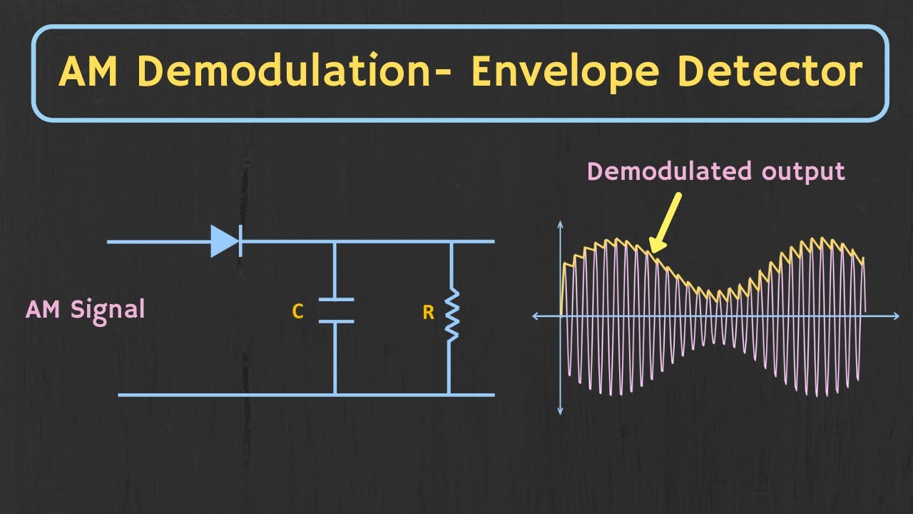
What is the purpose of the envelope detector in AM demodulation, and why is it not used in this experiment?
-The envelope detector is used in AM demodulation to extract the original message signal from the modulated AM signal by detecting the envelope of the waveform. It is not used in this experiment because the focus is on demonstrating modulation rather than demodulation.
Outlines

This section is available to paid users only. Please upgrade to access this part.
Upgrade NowMindmap

This section is available to paid users only. Please upgrade to access this part.
Upgrade NowKeywords

This section is available to paid users only. Please upgrade to access this part.
Upgrade NowHighlights

This section is available to paid users only. Please upgrade to access this part.
Upgrade NowTranscripts

This section is available to paid users only. Please upgrade to access this part.
Upgrade Now


5.0 / 5 (0 votes)