How to design and implement a digital low-pass filter on an Arduino
Summary
TLDRThis video demonstrates how to design and implement a low-pass filter for Arduino projects to eliminate sensor noise. It starts by creating an artificial signal with a 2 Hz sine wave and 50 Hz noise, using the Discrete Fourier Transform to visualize frequency components. The video explains the first-order low-pass filter's transfer function and its cutoff frequency, illustrating its effect on various frequencies through a Bode plot. It further explores higher-order Butterworth filters for improved performance, highlighting the trade-off between attenuation and delay. The content encourages viewers to consider their filtering needs based on specific applications.
Takeaways
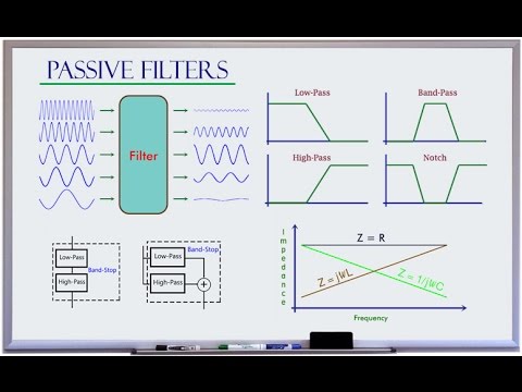
- 😀 Low-pass filters are essential for preserving low-frequency signals while reducing high-frequency noise in sensor applications.
- 🎵 A 2 Hz sine wave serves as the fundamental signal, while a 50 Hz sine wave represents unwanted noise in the analysis.
- 📊 The Discrete Fourier Transform (DFT) is used to visualize the frequency components of signals, helping identify noise characteristics.
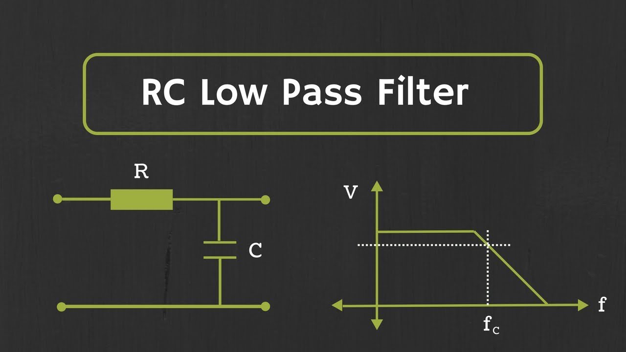
- 🔄 The first-order low-pass filter can be represented by the transfer function: ω₀ / (s + ω₀), where ω₀ is the cutoff frequency.
- ⚖️ A cutoff frequency of 5 Hz effectively preserves the 2 Hz signal while attenuating the 50 Hz noise, demonstrating the filter's functionality.
- 📈 The Bode plot illustrates how the filter's magnitude and phase response varies with frequency, highlighting its performance at different input frequencies.
- 🛠️ Implementing the filter on Arduino requires converting the transfer function into a difference equation suitable for real-time processing.
- 🚀 Higher cutoff frequencies can be set to allow for more significant signal components but may introduce a broad transition band, leading to partial attenuation.
- ✨ Butterworth filters offer improved performance over first-order filters by providing better attenuation and smaller transition bands as the order increases.
- ⌛ Higher-order filters, such as second-order Butterworth filters, offer better filtering but come with increased signal delay, requiring careful consideration in applications.
Q & A
What is the main purpose of the video?
-The video aims to teach viewers how to design and implement a low-pass filter for Arduino projects, specifically to reduce noise in sensor measurements.
What types of signals are used to test the low-pass filter?
-An artificial signal composed of a 2 Hz sine wave representing the fundamental component and a 50 Hz sine wave representing unwanted noise is used for testing.
What is the transfer function of a first-order low-pass filter?
-The transfer function is represented by the formula ω₀ / (s + ω₀), where ω₀ is the cutoff frequency.
What cutoff frequency was chosen for the low-pass filter in the video?
-A cutoff frequency of 5 Hz was chosen to preserve the 2 Hz signal while attenuating the 50 Hz noise.
What does the Bode plot illustrate in relation to the filter?
-The Bode plot shows the magnitude and phase of signals that have passed through the filter as a function of frequency, demonstrating how the filter affects different frequencies.
Why is the transfer function not suitable for real-time signal processing on the Arduino?
-The transfer function is in a continuous form, and real-time filtering requires a discrete-time implementation, necessitating the conversion into update equations.
How does the transition band affect the performance of a low-pass filter?
-The transition band is a range of frequencies near the cutoff where signals are neither completely passed nor completely stopped, leading to partial attenuation rather than a sharp cutoff.
What is the benefit of using a Butterworth filter over a first-order filter?
-The Butterworth filter provides better attenuation of high frequencies and a smaller transition band, resulting in more effective filtering.
How does increasing the order of the Butterworth filter affect delay?
-Higher order Butterworth filters exhibit greater delay in the filtered signal, which can lead to lag and affect real-time applications.
What considerations should be made when designing a low-pass filter?
-Designers need to balance the attenuation characteristics of the filter with the delay it introduces, ensuring it meets the requirements of the specific application.
Outlines

Esta sección está disponible solo para usuarios con suscripción. Por favor, mejora tu plan para acceder a esta parte.
Mejorar ahoraMindmap

Esta sección está disponible solo para usuarios con suscripción. Por favor, mejora tu plan para acceder a esta parte.
Mejorar ahoraKeywords

Esta sección está disponible solo para usuarios con suscripción. Por favor, mejora tu plan para acceder a esta parte.
Mejorar ahoraHighlights

Esta sección está disponible solo para usuarios con suscripción. Por favor, mejora tu plan para acceder a esta parte.
Mejorar ahoraTranscripts

Esta sección está disponible solo para usuarios con suscripción. Por favor, mejora tu plan para acceder a esta parte.
Mejorar ahoraVer Más Videos Relacionados

5.0 / 5 (0 votes)
