Mastering OCI Networking - Scenario 1 (Hub and Spoke with OCI Firewall)- Part B
Summary
TLDRThis video demonstrates the setup of an urban topology with an OC FI wall deployed in a hub-and-spoke network. It covers the creation of three VCNs, side-to-side VPN configuration, and network routing validation using the network visualizer. The presenter explains DRG route table configurations for on-prem and spoke VCNs, dynamic routing, and firewall inspections. It also includes details on the use of load balancers, web servers, and how to validate traffic through trace paths and log checks, ensuring proper firewall routing and traffic flow across the network.
Takeaways
- 😀 Overview of the setup involving Urban Spook topology with an OCFI wall deployed in a Hub.
- 🌐 Explanation of three VCNS (VCNA as Hub, VCNB, and VCNC as spokes) and a Site-to-Site VPN connected to an on-prem CP.
- 🔄 Network validation is done using the Network Visualizer tool to check the connections between the on-prem network and the VCNS.
- 🛠 Detailed configuration of DRG (Dynamic Routing Gateway) route tables for on-prem, spoke VCNS, and the Hub VCN.
- 🔗 Static route configuration for future VCNs to connect through the Hub VCN.
- 🚧 Import route distribution helps automatically download routes learned from IPsec and VCN attachments.
- 📶 Traffic inspection is done via firewalls, routing traffic between on-prem networks and spoke VCNS through the Hub.
- 🚦 Configuration of private and public subnets in Hub VCN with default routes pointing to the firewall and internet gateway.
- 🖥 Load balancer setup in the public subnet for the web server, which is accessed through Oracle Cloud Infrastructure.
- 📊 Logs and TracePath are used to verify that traffic is being routed through the firewall correctly.
Q & A
What is the purpose of the setup shown in the video?
-The purpose of the setup is to demonstrate an urban spook topology using an OCI (Oracle Cloud Infrastructure) firewall, with a hub-and-spoke VCN (Virtual Cloud Network) model, side-to-side VPN, and DRG (Dynamic Routing Gateway) configuration for secure routing between on-premise and cloud environments.
What are the roles of the VCNA, VCNB, and VCNC in the topology?
-In the topology, VCNA acts as the Hub VCN, while VCNB and VCNC are spoke VCNs. Traffic from the spoke VCNs is directed to the Hub VCN for centralized routing and inspection.
How does the routing between on-prem and cloud networks work in this setup?
-Traffic from the on-prem network, which is in the 100.x.x.x range, is routed through a side-to-side VPN connection to the Hub VCN. The Hub VCN inspects the traffic and then forwards it to the spoke VCNs, ensuring secure and controlled routing.
How is the DRG configured in this setup?
-The DRG (Dynamic Routing Gateway) is configured with multiple route tables: one for the on-prem network, another for the spoke VCNs, and a third for the Hub VCN. The DRG uses static and dynamic routes to forward traffic between the different components of the network.
What is the significance of the 'import route distribution' feature?
-The 'import route distribution' feature allows automatic downloading of routes learned by the DRG. It simplifies routing configuration by dynamically importing routes from IPsec, virtual circuit attachments, and VCN attachments, and applying them to the route tables.
What is the purpose of creating a static route for the 172.16.0.0/16 CIDR range?
-The static route for the 172.16.0.0/16 CIDR range is created to ensure that any future VCNs spun up within this CIDR range are properly routed to the Hub VCN, facilitating centralized traffic control.
Why are separate route tables used for the public and private subnets in the Hub VCN?
-Separate route tables are used for the public and private subnets to ensure proper traffic segmentation. The public subnet routes to the internet gateway, while the private subnet routes traffic through a firewall and the dynamic routing gateway (DRG) for secure internal communication.
What is the role of the firewall in this setup?
-The firewall, deployed in the private subnet of the Hub VCN, inspects incoming and outgoing traffic between the on-prem network, the internet, and the spoke VCNs. It ensures that only authorized traffic is allowed through the network.
How is traffic inspection validated in this setup?
-Traffic inspection is validated by reviewing the DRG transit routing tables, performing trace paths to check if traffic flows through the firewall, and checking the firewall logs for details on source, destination, ports, and actions.
How is East-West traffic (traffic between spokes) handled?
-East-West traffic between spoke VCNs is routed through the Hub VCN, where it is inspected by the firewall before being sent to its destination. The trace path and firewall logs can be used to verify this flow.
Outlines

Esta sección está disponible solo para usuarios con suscripción. Por favor, mejora tu plan para acceder a esta parte.
Mejorar ahoraMindmap

Esta sección está disponible solo para usuarios con suscripción. Por favor, mejora tu plan para acceder a esta parte.
Mejorar ahoraKeywords

Esta sección está disponible solo para usuarios con suscripción. Por favor, mejora tu plan para acceder a esta parte.
Mejorar ahoraHighlights

Esta sección está disponible solo para usuarios con suscripción. Por favor, mejora tu plan para acceder a esta parte.
Mejorar ahoraTranscripts

Esta sección está disponible solo para usuarios con suscripción. Por favor, mejora tu plan para acceder a esta parte.
Mejorar ahoraVer Más Videos Relacionados

PENGERTIAN DAN PENJELASAN TOPOLOGI STAR
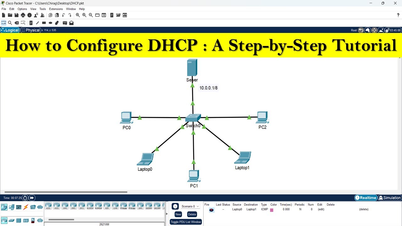
How to configure DHCP server | DHCP server configuration step by step
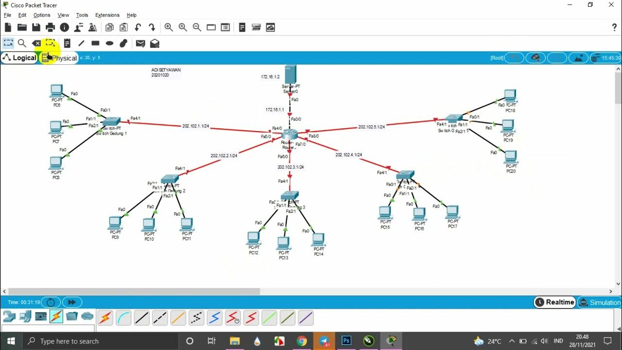
TUTORIAL MEMBUAT TOPOLOGI JARINGAN STAR DI GEDUNG 5 LANTAI MENGGUNAKAN CISCO PAKET TRACER

Konfigurasi Dasar Mikrotik ROS V7 untuk PPPoE dan Hotspot Voucher

Become An Azure Expert In 3 Easy Steps
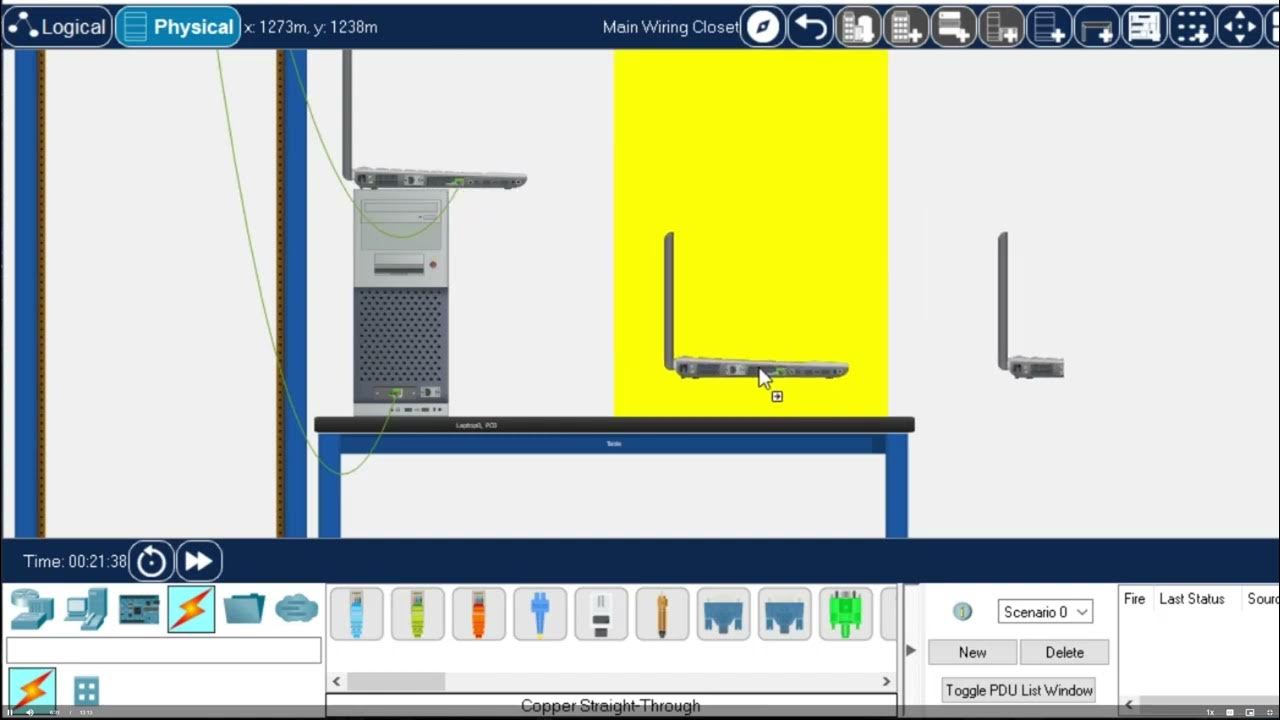
Getting Started in Cisco Packet Tracer - 2023
5.0 / 5 (0 votes)
