Multiplexers and DeMultiplexers
Summary
TLDRThis video script offers an insightful explanation of multiplexers and demultiplexers, essential components in digital signal processing. A multiplexer (MUX) is a digital switch that consolidates multiple inputs into a single output, allowing users to select the desired input source for an output device, such as a stereo system. Conversely, a demultiplexer (DEMUX) takes a single input and routes it to one of several outputs, useful for devices like printers. The script delves into the symbols and functions of these components, their practical applications in home electronics, and how they work in tandem. It also provides a detailed look at the internal circuitry of these devices, built from basic logic gates, and their configurations in simulation software, highlighting the enable pins and inverted outputs.
Takeaways
- 🔌 A multiplexer (MUX) is a digital switch that allows multiple inputs to be selected and sent to a single output.
- 🎧 Common uses for multiplexers include routing audio from various sources like MP3 players, laptops, and satellite boxes to a single output device like speakers.
- 🔄 The opposite of a multiplexer is a demultiplexer (DEMUX), which takes a single input and routes it to multiple outputs, such as printing a document to various devices like printers or fax machines.
- 🔗 Multiplexers and demultiplexers often work together, with the former combining multiple inputs into one signal for transmission and the latter routing that signal to the correct output.
- 📊 The number of inputs or outputs in a multiplexer or demultiplexer is always a power of 2 (e.g., 2, 4, 8, 16), requiring a corresponding number of selector inputs to determine the active path.
- ⚙️ Internally, multiplexers are constructed using basic logic gates like AND, OR, and NOT gates, with the specific configuration depending on the number of inputs and outputs.
- 🛠️ To select a specific input in a multiplexer, the selector inputs are set to enable the corresponding logic path, allowing the desired input signal to pass through to the output.
- 🔄 In a demultiplexer, the process is reversed; selector inputs determine which output path is enabled, allowing the single input signal to be routed to the desired output.
- 💡 The concept of multiplexing is essential for efficient data transmission, as it allows multiple signals to be sent over a single communication line, reducing the need for physical wiring.
- 📚 Understanding the operation of multiplexers and demultiplexers is fundamental to grasping digital communication systems and their applications in everyday technology.
Q & A
What is a multiplexer?
-A multiplexer is a digital switch that allows multiple inputs and a single output, enabling the selection of which input signal is sent to the output.
How does a multiplexer select which input to send to the output?
-A multiplexer uses a set of selector inputs, typically binary, to determine which of the multiple inputs is connected to the single output.
What is the abbreviation for a demultiplexer?
-The abbreviation for a demultiplexer is 'DEMUX', which is the opposite of a multiplexer.
How does a demultiplexer differ from a multiplexer?
-A demultiplexer has a single input and multiple outputs, allowing it to select which output should receive the input signal.
What is the relationship between multiplexers and demultiplexers in a system?
-Multiplexers and demultiplexers often work together, with the multiplexer combining multiple inputs into a single output line, and the demultiplexer then routing that single input to the correct output among many.
How are multiplexers and demultiplexers represented in circuit diagrams?
-In circuit diagrams, multiplexers and demultiplexers are represented by trapezoidal symbols. A multiplexer (MUX) has multiple inputs and a single output, while a demultiplexer (DEMUX) has a single input and multiple outputs.
What is the significance of the number of inputs in a multiplexer?
-The number of inputs in a multiplexer is always a power of 2 (e.g., 2, 4, 8, 16), which corresponds to the number of binary combinations needed to select one input out of the many.
Can you explain how a 4-to-1 multiplexer works using basic gates?
-A 4-to-1 multiplexer uses a combination of AND, OR, and NOT gates to select one of the four inputs based on two selector inputs. The selector inputs determine which path is enabled, allowing the corresponding input to pass through to the output.
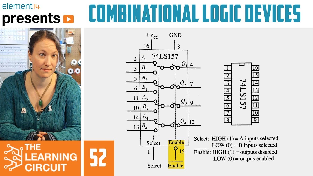
What is the purpose of the enable pin on a multiplexer chip?
-The enable pin on a multiplexer chip is used to activate the chip. It is active low, meaning the chip is enabled when a 0 is sent to this pin.
How does the number of selector inputs relate to the number of outputs in a demultiplexer?
-The number of selector inputs in a demultiplexer is determined by the number of outputs. For example, to select one output from 16, you would need 4 selector inputs, as 4 bits are required to represent 16 different combinations.
What does the bubble symbol next to the output of a multiplexer or demultiplexer indicate?
-The bubble symbol next to the output of a multiplexer or demultiplexer in a circuit diagram indicates that the output is inverted, meaning a 0 input will result in a 1 output, and vice versa.
Outlines
🔌 Introduction to Multiplexers and Demultiplexers
The speaker begins by introducing the concept of multiplexers (MUX) and demultiplexers (DEMUX), explaining that a multiplexer is a digital switch that consolidates multiple input signals into a single output. Examples include connecting various devices like an MP3 player or a laptop to a stereo system. The multiplexer is represented by a diagram with four inputs and one output, where the output can be selected from the inputs. The video also touches on the concept of demultiplexers, which work in reverse, taking a single input and distributing it to multiple outputs. The speaker uses the example of sending a document to various output devices like a printer or a fax machine. The symbols for both MUX and DEMUX are shown, highlighting their respective functions and the way they are represented in circuit diagrams.
🛠️ Inside a Multiplexer: Basic Gates and Logic
This section delves into the internal workings of a multiplexer, revealing that it is constructed from fundamental logic gates such as AND, OR, and NOT gates, as well as inverters. The speaker explains the logic behind a 4-to-1 multiplexer, where four inputs are selected and sent to a single output based on the settings of two selector inputs. The concept of using binary signals to enable or disable gates within the multiplexer is discussed, with a focus on how a NAND gate behaves when provided with a zero input. The speaker uses a table to illustrate the relationship between the selector inputs and the corresponding output, demonstrating how specific input combinations result in the transmission of a particular input signal to the output.
🔄 Demultiplexers: Function and Internal Structure
The final paragraph shifts focus to demultiplexers, explaining their function as the counterpart to multiplexers. A demultiplexer takes a single input and routes it to one of several outputs, determined by the settings of selector inputs. The internal structure of a demultiplexer is explored, which, like a multiplexer, is composed of basic logic gates. The speaker uses a table to demonstrate how different combinations of selector inputs result in the input signal being sent to specific output lines. The concept of power-of-two relationships between inputs and outputs for both multiplexers and demultiplexers is reiterated, with an explanation of how the number of selector inputs is determined by the number of possible output combinations. The video concludes with a brief look at how multiplexers and demultiplexers are represented in a simulation software, highlighting the enable pins and the concept of active-low signals.
Mindmap
Keywords
💡Multiplexer (MUX)
💡Demultiplexer (DEMUX)
💡Digital Switch
💡Input and Output
💡Power of 2
💡NAND Gate
💡AND Gate
💡Inverter Gate
💡Selectors
💡Enable Pin
Highlights
A multiplexer is a digital switch that allows multiple inputs to be selected for a single output.
Examples of multiple inputs include an MP3 player, laptop, sound card, digital satellite box, or cable TV box.
A multiplexer is useful for selecting which input device's signal is sent to a single output device, like stereo speakers.
Demultiplexers (or 'DEMUX') are the opposite of multiplexers, having a single input and multiple outputs.
Demultiplexers can route a single input signal to the correct output device, such as a printer or fax machine.
Multiplexers and demultiplexers often work together, with the former combining signals and the latter routing them to specific outputs.
In telecommunications, multiplexing combines multiple signals into one high-speed line, while demultiplexing routes them to the correct recipient.
A multiplexer is constructed from basic logic gates, such as AND, OR, and NOT gates.
The number of inputs in a multiplexer is always a power of 2 (e.g., 2, 4, 8, 16).
Selectors are used to determine which input is routed to the output in a multiplexer.
A demultiplexer is also made from basic logic gates and has a single input with multiple outputs.
The number of outputs in a demultiplexer is a power of 2, and the number of inputs is determined by the number of outputs.
In a multiplexer, enabling a specific input path requires setting all other inputs to '1'.
The operation of a demultiplexer is similar to that of a multiplexer, but in reverse, selecting an output path for a single input.
Multiplexers and demultiplexers can be visualized and simulated using software like Multisim.
In practical applications, multiplexer chips have an enable pin that needs to be set to '0' to activate the chip.
Demultiplexer chips may have inverted outputs, indicated by a bubble on the output pin, which is a design choice for simplicity inside the chip.
Both multiplexers and demultiplexers are essentially switches that can be controlled to direct signals to specific inputs or outputs.
Transcripts
in this video I'm going to talk about
multiplexers and demultiplexers
this is a diagram of a multiplexer a
multiplexer is really just a digital
switch that allows multiple inputs so
here are my multiple inputs right here I
have four inputs my mp3 player my laptop
sound court card and so forth I might
have a digital satellite box or a cable
TV box and I want to be able to select
which of these inputs goes to my output
in this case my output might be my
stereo speakers right here so a
multiplexer has multiple inputs and a
single output and you can select which
of these inputs goes to your output and
this actually might be something that
you have connected at home at least I do
I have a bunch of things to connect it
into my stereo and I can select which
one I want to play over my my sound
system to play over my speakers so again
multiplexing or a multiplexer is several
inputs multiple inputs a single output
and you can select which one of those
inputs goes to that output
ad multiplexer or D max as it's
sometimes abbreviated as is the opposite
of a multiplexer as you might have
expected so I have one input here's my
one input this very old-looking computer
right here my single input and I have
several output choices so perhaps I have
a document that I want to print and I
can select which of these outputs I want
to send my document it might be my laser
printer a fax machine and jet or a pen
plot or so forth so ad multiplexer it's
the opposite of a multiplexer I have one
input and multiple output and perhaps
you noticed that the multiplexer
abbreviated MUX was was the same symbol
as the D multiplexer but it was the
other way around so my D multiplexer
they're both trapezoids one input
multiple outputs that's my D multiplexer
my multiplexer was the exact
in terms of its symbol it looked like
that looked like that right it was had
multiple inputs multiple inputs and a
single output that was my multiplexer
abbreviated MUX this is my D multiplexer
a single input multiple outputs and you
can select where that output should go
where you have a bunch of different
destinations
as you might have expected multiplexers
and demultiplexers
often work together so here on the Left
I have a multiplexer showing multiple
inputs combined into one output now this
output might be like a high-speed
fiber-optic cable or something like that
and on the other side I have a d
multiplexer taking that single input and
routing it to the correct output so
multiplexer multiple inputs I have a
bunch of inputs here one output D
multiplexer that single input and it's
it's sending it to the correct output
and in this illustration it shows that I
have a bunch of conversations all
happening at once and these could be
conversations between people or
computers or whatever and they're all
getting combined into this single
high-speed line and then it's getting
routed to the correct
recipient on the other end using
multiplexing to combine the inputs and
de-multiplexing to take the input and
send it to the correct output
here's another diagram showing a similar
thing actually as the previous diagram
where I have a multiplexer in this case
it's called a multiplexer demultiplexer
because I might have several inputs
that's the multiplexing part several
inputs going to a single output a fast
line as it says and then getting
demultiplexed going to the correct
output perhaps so that's the D
multiplexing part but then on this side
the communication might go the other
direction as well where I have several
inputs so this box is actually a
multiplexer demultiplexer here I have
might have several inputs
going to my fast
and then again getting sent to my
correct output so depending on which way
the communication is going the these
boxes could either be multiplexing or D
multiplexer either combining several
inputs to a single output or taking that
single input and sending it to the
correct output I just thought this was a
nice additional diagram to add
now it's time to look inside a
multiplexer and see how they work a
multiplexer is just built out of basic
gates here's a three input and gate for
input or gate here's a couple of knock
dates a couple of inverter gates and
let's see what's going on inside here so
this is a 4 to 1 multiplexer I have 4
inputs the number of inputs is always
going to be some power of 2 it's always
going to be 2 to the n in this case it's
2 squared 2 squared is 4 but it could be
4 inputs a to put 16 and so forth and on
the bottom here this is out how I select
which of these inputs goes to the output
so just real quick before we get into
how this works just a jog your memory
about how and gates work if I send in a
0 to a NAND gate that output is always
going to be 0 no matter what the input
is so let's let's say I have a switch
here called an e if I send in a zero to
the other input the outputs always going
to be 0 so if you send in a zero to a
NAND gate you've effectively disabled a
NAND gate it's always going to be 0
here's another end date this time I'm
going to send in a 1 to this and gate
now I have a switch called a so I'm
ending together a with a 1 that output
is going to be whatever a is in other
words if I switch a on I'll get a 1 out
if I switch a to the 0 I'll get a 0 out
so effectively if I make all the other
inputs to a NAND gate ones the output
will be whatever data is coming in on
line a and that's the basics that's the
basis for how these things work in other
words if I want d0 to be transmitted to
my output I have got to make sure that
all the other inputs both these inputs
are ones well how am I going to do that
look at the table right here it says if
I make a and B both zeros my output will
be d0 let's see why if I if I make these
both zeros I'm nodding them right here
so that means they're gonna be ones I'll
have a 1 going into both of these things
and so yes in fact whatever d0 is will
be my output and if we take a quick look
at the other end dates at the same time
let's see remember I have if I have 0 is
going in so these two lines will be 0
let's just check out the other ones real
quick so this would be a 1 0 this would
be a
0 1 and this would be a it looks like I
have a 0 0 yeah so notice when the
inputs are 0 0 the only the only and
gate that's enabled the only one that
has two ones is this top one right here
and I think if you if you follow the
other
examples like if I wanted to check out
what happens when B is 0 and a is a 1 I
think you will find that d1 will get 2
ones and the output will come from this
and gate it's really not that
complicated but I hopefully you get
what's going on here so again a
multiplexer just built out of basic
hands and or gates and it's always going
to be some power of 2 in this case I
have 4 inputs and I need to
two digits to select which of the inputs
goes to the output
imagine I had 8 inputs let's say I had 2
to the 3rd or 8 inputs how many how many
different
inputs what I need on the bottom to
select which one I which one went to the
output well it would be 3 why could I
need 3 well because in binary you need 3
bits to get 8 possible combinations from
0 0 0 to 1 1 1 that's 0 to 7 that's 8
possible combinations so I already need
3 inputs on the bottom for my selectors
if I had eight data inputs and of course
if I had sixteen data inputs I would
need four different selectors a B C and
D perhaps on the bottom hopefully this
makes sense now let's take a look at D
multiplexers so here is what the inside
of a demultiplexer looks like and
amazingly it is also made out of basic
AIDS so here are a bunch of three input
NAND gates here's a couple of not gates
or inverter gates and let's see how this
works remember D multiplexer I have my 1
input source and I can decide where I'm
going to send that and put which one of
these 4 outputs and of course as you
guessed it the number of outputs is
always going to be a power of 2 it's
going to be 2 to the something to be n 2
4 8 16 32 and so forth and the number of
inputs is is n if well well go so let's
say that I want my output to go to d0
well as you already know if you want to
transmit whatever the input is I've got
to make the other inputs both ones well
how am I going to do that let's look at
this table right here if I make them
both zeros let's do that I'll make a and
B both zeros so if a 0 and B is a 0
coming out of here I will have a 1 and 1
and going into here yes I have two ones
so my my input coming from X will be
transmitted to d0 if I make them both 0
so yes the output will be
d0 the others will be just zeros if I
want my data to come out of d1 or to be
sent to d1 I make be a 0 and a 1 and you
can follow through this this is very
similar to the multiplexer diagram the
whole idea is if you want to enable a
NAND gate you've got to send all of the
other inputs ones and then this last imp
in this case it will be coming from X
whatever X's will be transmitted to your
output and again I'm over here this is
the diagram of a demultiplexer one input
multiple outputs and you can select
where your input gets sent by using
these selectors on the bottom and if I
have let's say for example let's say I
have
16 outputs also known as two to the
fourth I will need four different input
selectors right because to get 16
possible numbers in binary I need 4 bits
I need to go from 0 0 0 0 to 1 1 1 1
that's from 0 to 15 that's 16 possible
combinations alright well hopefully that
makes sense a couple more slides to go
so here is a look at what a multiplexer
will look like if you work in multi sim
and here's a bunch of different
multiplexer chips here's a 4 input
multiplexer right I have 4 inputs and
you can see that I will need 2 switches
to select which of these 4 inputs I want
and here is an 8 input multiplexer in
this case I'm going to need 3 inputs to
select which which of these inputs goes
to my output and of course if I have a
16 input multiplexer I'm going to need 4
switches this this other little pin here
this is an enable pin and notice it has
a little bubble a little circle right
there that circle means in order to
enable this particular chip you need to
send it a 0 that little circle indicates
that it wants a 0 to do its job so
another way of saying it is it's active
low you will activate this chip if you
send it a 0 notice that all the chips
have have that little enable right there
so in order for this chip to work
properly and I don't know why they
designed it this way in addition to your
inputs and selectors and all that kind
of stuff you have to send this little
activation pin a 0 all right let's take
a look at Dien bulky flexors finally
let's take a look at the diagrams of
demultiplexers so this is what it's
going to look like in multi-sim if you
work with demultiplexers here i have a a
for output d multiplexer and of course i
need two switches to determine which
output it goes to this is my input right
here here I have a one to eight D
multiplexer then this is my data input
line and I need of course three switches
to determine which of these outputs it
goes to and then I have my sixteen
twenty multiplexer I need four switches
to determine where my data is going to
sent be sent from these sixteen right
four switches 0 0 0 0 2 1 1 1 1 is 15 or
rather 16 possible combinations i need
16 combinations to determine which of
these 16 outputs it's going to go to and
notice also at the end these little
bubbles here mean that the output is
going to be inverted it's done that I
it's I know that seems weird some chips
are built like this and I presumably
it's because it made the logic inside
the chip a little bit simpler you really
don't need to worry about that too much
with multiplexers we'll talk more about
that when we talk about other chips so
hopefully you have a basic understanding
of the difference between a multiplexer
and a demultiplexer again they're just
switches multiplexer multiple inputs 1
output D multiplexer 1 data input
multiple outputs and you can select
where you want that output to go all
right that's it
Ver Más Videos Relacionados
PENGERTIAN KOMPONEN KOMPUTER INPUT PROSES OUTPUT STORAGE
81. OCR GCSE (J277) 2.4 Simple logic diagrams
Parts Of A Computer And Their Functions
33. CAMBRIDGE IGCSE (0478-0984) 3.2 Output devices
Komponen Penunjang Single Board Controller | Sistem Komputer | Informatika XII
2021 Grade 10 Module 1.3) Hardware
5.0 / 5 (0 votes)