Electrical Engineering: Basic Laws (11 of 31) Kirchhoff's Laws: A Medium Example 2

Michel van Biezen
6 Nov 201508:55

Summary

TLDRThis video demonstrates how to apply Kirchhoff's laws to solve a two-loop circuit with a voltage source and three resistors. It illustrates using Kirchhoff's current and voltage laws to derive three equations, allowing calculation of currents through all resistors. The analysis starts by assuming current directions and applying Kirchhoff's first law at a node. Then, Kirchhoff's second law is applied to each loop to derive voltage equations. The resulting equations are solved simultaneously to find the currents. Although other methods may be easier, this approach effectively illustrates Kirchhoff's laws in action.

Takeaways

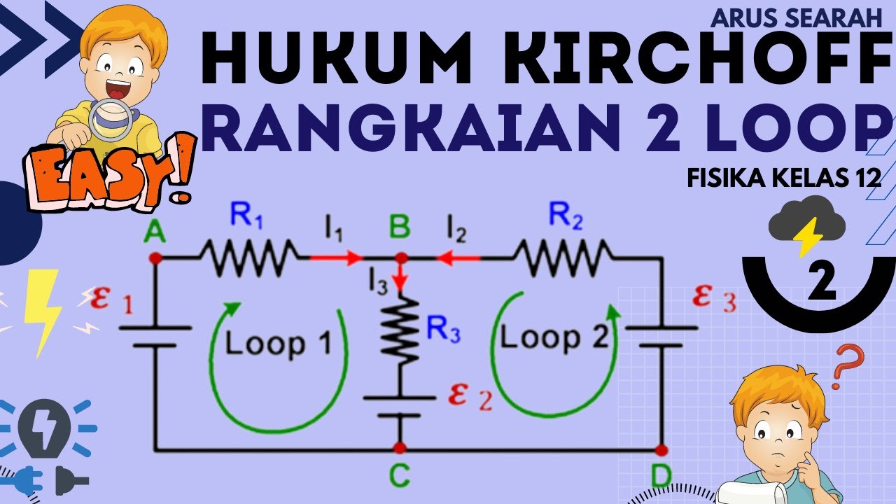
  • 🔋 The circuit involves a two-loop configuration with a voltage source and three resistors.
  • 🌀 Kirchoff's Laws are used to solve for the currents in all three resistors, providing a clear example of applying these rules.
  • 🔄 The first assumption involves the direction of current flow through the three resistors, and if the assumptions are incorrect, negative values indicate the actual direction.
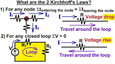
  • 📏 Kirchoff's First Law (Current Law) states that the sum of currents entering a node must equal the sum of currents leaving that node.
  • 🔁 A node is identified where current i1 enters, and currents i2 and i3 leave, leading to the first equation: i1 = i2 + i3.
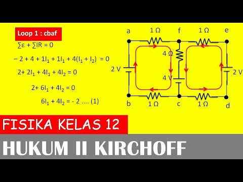
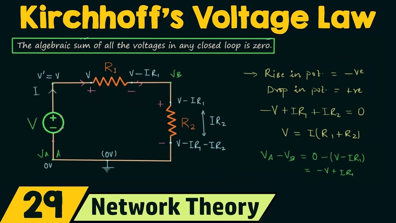
  • 🔋 Kirchoff's Second Law (Voltage Law) is applied to both loops, stating that the sum of voltage drops and rises around a loop must equal zero.
  • 🔄 Loop 1 results in a voltage rise across the battery and voltage drops across the resistors, leading to the second equation.
  • 🔁 Loop 2 also gives another equation, involving voltage rises and drops across the resistors, forming the third equation.
  • 🔧 The system of equations is solved by substitution and elimination, ultimately calculating i2 and i3.
  • 💡 The solution shows that i1 = 3A, i2 = 2A, and i3 = 1A, validating the node current splits and direction assumptions.

Q & A

  • What is the purpose of using Kirchhoff's laws in this circuit analysis?

    -Kirchhoff's laws are used to solve for the current flowing through all three resistors by creating equations based on the sum of currents at a node and the sum of voltage drops in loops. This method is illustrated to show how to solve a circuit that could also be solved using simpler methods, like finding equivalent resistance.

  • What are Kirchhoff's two laws mentioned in the script?

    -The first law (Kirchhoff's Current Law) states that the sum of currents entering a node must equal the sum of currents leaving the node. The second law (Kirchhoff's Voltage Law) states that the sum of voltage rises and drops around any closed loop must add up to zero.

  • How are the current directions assumed in this circuit?

    -The current directions are assumed arbitrarily for each resistor. If the actual direction differs, the result will be a negative value, indicating that the assumed direction was incorrect. However, this won't affect the solution.

  • What is the first equation derived from Kirchhoff's Current Law (KCL)?

    -The first equation derived from KCL is i1 = i2 + i3, where i1 is the current entering the node, and i2 and i3 are the currents leaving the node.

  • How are the two loops defined in the circuit?

    -The two loops are defined by tracing a path around the circuit. Loop 1 is traced clockwise around the first part of the circuit, and Loop 2 is traced counterclockwise around the second part of the circuit. The sum of voltages in each loop must equal zero according to Kirchhoff's Voltage Law.

  • What is the second equation derived from Loop 1?

    -The second equation from Loop 1 is 30 - 8i1 - 3i2 = 0. This represents the voltage rise from the 30V source and the voltage drops across the 8-ohm and 3-ohm resistors in the direction of the current.

  • What is the third equation derived from Loop 2?

    -The third equation from Loop 2 is 3i2 - 6i3 = 0. This represents the voltage rise across the 3-ohm resistor (going against the current) and the voltage drop across the 6-ohm resistor (in the direction of the current).

  • How are the three equations solved simultaneously?

    -To solve the system, i1 is substituted into the second equation to get two equations with i2 and i3. Then, the equations are manipulated to eliminate one variable, allowing for the solution of i2 and i3. Finally, i1 is found using the first equation (i1 = i2 + i3).

  • What are the final values of the currents i1, i2, and i3?

    -The final values are i1 = 3A, i2 = 2A, and i3 = 1A. These values satisfy both Kirchhoff’s Current Law and Voltage Law, meaning the solution is correct.

  • What would happen if the directions of the currents were assumed incorrectly?

    -If the current directions were assumed incorrectly, the final solution would give a negative value for the current, indicating that the actual current flows in the opposite direction to what was assumed. However, this doesn't affect the validity of the results.

Outlines

00:00

🔧 Introduction to Kirchoff’s Laws and Circuit Analysis

This paragraph introduces a two-loop circuit and outlines the process for solving it using Kirchoff’s laws. The circuit consists of a voltage source and three resistors. While other methods like finding equivalent resistance might be easier, the problem is being solved with Kirchoff’s laws for illustrative purposes. The goal is to determine the current through each resistor. The directions of the currents through each resistor are assumed, noting that a negative result would indicate the current is in the opposite direction. The paragraph also introduces the first of Kirchoff’s laws: the sum of currents entering a node must equal the sum of currents leaving the node, forming the basis for the first equation, i1 = i2 + i3.

05:01

🔄 Applying Kirchoff’s Voltage Law to Loop Analysis

In this section, the focus shifts to Kirchoff’s second law, which states that the sum of all voltages around a loop must be zero. Two loops are identified in the circuit, and the voltage rises and drops around each loop are analyzed. For Loop 1, the voltage rise from the battery is balanced by the voltage drops across resistors. The first loop equation is derived as 30 - 8 * i1 - 3 * i2 = 0. Similarly, in Loop 2, the second equation is derived by analyzing the voltage changes across the resistors, resulting in 3 * i2 - 6 * i3 = 0. With three equations now formulated (one from Kirchoff’s current law and two from voltage law), the groundwork is laid for solving the currents through the circuit.

Mindmap

Keywords

💡Kirchhoff's Laws

Kirchhoff's Laws are fundamental principles in electrical circuits, consisting of two laws: Kirchhoff's Current Law (KCL) and Kirchhoff's Voltage Law (KVL). In the video, these laws are used to solve for the currents in a two-loop circuit. KCL states that the total current entering a node must equal the total current leaving it, while KVL states that the sum of voltages in any closed loop must equal zero. These laws are applied to derive equations that describe the circuit's behavior.

💡Node

A node in an electrical circuit is a junction where two or more components are connected. In the video, a specific node is chosen to apply Kirchhoff's Current Law, where the incoming current (I1) is set equal to the sum of the outgoing currents (I2 and I3). This concept is central to understanding how currents are distributed in a circuit.

💡Loop

A loop in circuit theory refers to any closed path through a circuit. The video discusses two loops in a two-loop circuit, and Kirchhoff's Voltage Law is applied to each loop. By summing the voltage rises and drops around these loops, equations are formed that help solve for the currents in the circuit's resistors.

💡Resistor

A resistor is a passive electrical component that limits the flow of electric current. In the video, three resistors are connected in the circuit, each contributing to voltage drops based on the current flowing through them. The resistors have values (e.g., 8 ohms, 3 ohms, 6 ohms), and the current through each resistor is calculated using Kirchhoff's Laws.

💡Voltage Source

A voltage source is a device that provides electrical potential energy to a circuit, causing current to flow. In the video, a 30-volt voltage source drives the current through the circuit. It creates a potential difference that is crucial for calculating voltage rises and drops in the loops.

💡Current

Current is the flow of electric charge through a conductor. The video focuses on solving for the currents (I1, I2, and I3) through three different resistors. These currents are found by applying Kirchhoff's Current Law at a node and Kirchhoff's Voltage Law around the loops, illustrating how current distributes in a circuit.

💡Voltage Drop

A voltage drop occurs when electrical energy is lost as current flows through a resistor or other component. In the video, the voltage drops across the resistors are calculated based on the current and resistance, as per Ohm's Law (V = IR). These drops are crucial for applying Kirchhoff's Voltage Law in each loop.

💡Simultaneous Equations

Simultaneous equations are a set of equations that are solved together because they share variables. In the video, three equations are derived using Kirchhoff's Laws, and these equations must be solved simultaneously to find the values of I1, I2, and I3. This step is critical for determining the behavior of the circuit.

💡Assumed Current Direction

In circuit analysis, the direction of current flow is often assumed and marked with arrows. In the video, the directions of I1, I2, and I3 are initially assumed, and it's noted that if the assumptions are incorrect, the resulting current values will be negative, indicating the actual direction is opposite. This concept helps in correctly analyzing circuits without prior knowledge of current direction.

💡Voltage Rise

A voltage rise occurs when moving from a lower to a higher potential within a circuit, such as when crossing a voltage source in the direction of its polarity. In the video, a 30V voltage rise is noted when crossing the voltage source in Loop 1. This rise contributes to the application of Kirchhoff's Voltage Law in calculating the total voltage around the loop.

Highlights

Introduction to Kirchhoff's laws and their application to a two-loop circuit.

The circuit consists of a voltage source and three resistors: Resistor 1, Resistor 2, and Resistor 3.

Discussion on alternative methods like equivalent resistance for easier solving, but focus is on illustrating Kirchhoff's laws.

Assumption of current directions in the resistors, and how getting a negative result indicates the direction is opposite.

Kirchhoff's first law (Junction Rule): The sum of currents entering a node equals the sum of currents leaving the node.

Application of the Junction Rule at a specific node: i1 = i2 + i3.

Defining two loops for applying Kirchhoff's second law (Loop Rule) around the circuit.

Kirchhoff’s second law (Loop Rule): The sum of voltage rises and drops around a loop must equal zero.

First equation from Loop 1 using Kirchhoff's second law: 30 - 8*i1 - 3*i2 = 0.

Second equation from Loop 2 using Kirchhoff's second law: 3*i2 - 6*i3 = 0.

Combining the current equation (i1 = i2 + i3) into the loop equations to solve for currents i1, i2, and i3.

Solving the system of equations using substitution and elimination to find i2 = 2A, i3 = 1A, and i1 = 3A.

Verification of the solution: Currents in the branches (i2 = 2A, i3 = 1A) add up to the total current i1 = 3A.

Explanation of how this method demonstrates the use of Kirchhoff's laws, despite other simpler methods available.

Summary of the process: Using Kirchhoff's first and second laws to form three equations, then solving them simultaneously to find the current through each resistor.

Transcripts

play00:00

welcome to alector line here we have

play00:03

another example of how to apply Kirk's

play00:05

laws here is a two-loop circuit we have

play00:08

a voltage source we have three resistors

play00:10

now we know that this problem can be

play00:12

solved much easier probably using the

play00:15

methodology of finding the equivalent

play00:17

resistance and then finding the total

play00:19

current and then see how the current

play00:20

branches out in the various branches but

play00:24

in order to illustrate how to use kirov

play00:26

laws this is a good example to use here

play00:30

we need to find the current through all

play00:32

three resistors we have resistor one

play00:34

resistor 2 and resistor 3 and one

play00:37

voltage source we can see that through

play00:39

the first resistor let's say that we

play00:41

assume that there will be a current

play00:43

flowing through this resistor in this

play00:45

direction then here we have a current

play00:47

flowing through this resistor let's

play00:49

assume it's going to be in this

play00:50

direction and here we have a current

play00:52

flowing uh through this Branch right

play00:55

here and through this resistor let's

play00:56

call that I sub3 and again assume that

play00:59

will be direct the direction of the

play01:01

current now we could be wrong here it

play01:03

could be that the direction of current

play01:05

is in a different direction opposite of

play01:06

what we drew but that's quite all right

play01:09

if we did we'll end up with a negative

play01:10

answer which that indicates the arrow

play01:12

was drawn in the wrong direction

play01:14

although with the voltage source having

play01:16

the positive end on this side the

play01:17

negative end on this side it can be

play01:19

almost certain that the we can assume

play01:22

that the current will be in this

play01:23

direction as we have drawn the first law

play01:26

of kirov states that we can add up all

play01:29

all the currents entering a

play01:33

node and that must equal all the

play01:35

currents leaving that

play01:39

node and if we use that law we can take

play01:42

a look and see how about this node right

play01:44

here let's pick this Noe we can see that

play01:46

we have i1 entering that node and I2 and

play01:49

I3 leaving that node based upon that we

play01:51

have our first equation that i1 must

play01:54

therefore equal I2 + I3 that's equation

play01:59

number one

play02:02

now we have two Loops we have a loop and

play02:04

let's say that we go around the loop in

play02:06

this direction call that Loop

play02:08

one and the second Loop let's say we're

play02:10

going to go around the loop in this

play02:12

direction let's call that Loop

play02:14

two we need to start at some node let's

play02:17

say we started this node right here for

play02:19

both loops and we'll go around this Loop

play02:22

in this direction we'll go around this

play02:23

Loop in this direction and the second

play02:25

law of Kirk house says that the sum of

play02:28

all the voltages around any Loop must

play02:31

add up to zero which means when we add

play02:33

up all the voltage Rises and all the

play02:35

voltage drop around Loop one they should

play02:37

add up to zero when when we add up all

play02:39

the voltage Rises and voltage drops

play02:41

around Loop two they should add up to

play02:43

zero as well and that will give us the

play02:45

other two equations we're looking for

play02:47

because after all we're trying to solve

play02:49

for three currents therefore we will

play02:51

need three equations to solve this

play02:53

problem starting at this node going

play02:55

around the loop like this we go across a

play02:57

30 volt battery that is a 30 volt rise

play03:01

now we go across this resistor in the

play03:03

same direction as the current that means

play03:04

we have a voltage drop of minus the

play03:07

resistance 8 times the current

play03:10

i1 then we go to this uh note right here

play03:14

through this resistor along the same

play03:17

direction as the current again that's a

play03:19

voltage drop so minus the Resistance 3

play03:21

ohms times the current I2 now we have

play03:25

made a complete Loop therefore this

play03:27

should add up to zero and there's

play03:28

equation number two

play03:32

the second Loop starting again from here

play03:35

we go across this resistor but now

play03:36

notice we go against the current flow

play03:38

therefore that's a voltage rise that' be

play03:41

3 *

play03:45

I2 here we go across this resistor in

play03:47

the same direction of the current that's

play03:49

a voltage drop minus the resistance 6

play03:52

times the current I3 and now we've made

play03:55

a complete Loop that must add up to

play03:58

zero

play04:00

notice we now have three equations one

play04:03

two and three obtained by using both

play04:05

laws of kirkov now we need to solve

play04:08

those simultaneously the best way to do

play04:10

that is to take the current equation

play04:12

which is now already expressed as one

play04:15

current in terms of the other two

play04:17

currents and we can then substitute that

play04:19

into the other two equations in this

play04:21

case we only have to substitute it into

play04:23

one equation because the second equation

play04:25

does not include I sub one that will now

play04:27

give us the following two equations

play04:30

equation number two now changes to 30 -

play04:33

8 * i1 and we know from this equation

play04:36

that i1 is equal to I2 +

play04:42

I3 minus 3

play04:45

I2 equal to Zer the second equ or the

play04:48

third equation now becomes well nothing

play04:51

changes it is still 3 I2 - 6 I3 is equal

play04:57

to

play04:58

Z well we should do now is we need to

play05:01

solve these two equations simultaneously

play05:03

let's put them into a different format

play05:04

we'll have the eyes on the left side and

play05:06

any constants on the right side so for

play05:08

the first equation the 30 will move to

play05:10

the right side become a minus 30 we have

play05:12

a minus 8 I2 minus 3 I2 that is a - 11

play05:18

I2 - 8 I3 is equal to Aus 30 and since

play05:25

all the terms in there are negative we

play05:27

can simply multiply both sides by Nega 1

play05:29

and and turn everything into a positive

play05:31

so there's the equation number two in

play05:33

the format with all the eyes on the left

play05:35

side and the constant on the right side

play05:37

now we can take the third equation

play05:39

equation number three and write it as 3

play05:42

I2 - 6 I3 is equal to

play05:47

zero now we need to solve these

play05:50

simultaneously usually the easiest way

play05:52

is to go ahead and try to manipulate the

play05:54

two equations multiplying times some

play05:56

constant so that when we add the two

play05:58

equations together we eliminate one of

play06:00

the variables we notice that the that

play06:02

the common uh if we multiply this by

play06:06

three and this by four we we get 24 we

play06:09

get a positive 24 a negative - 24 so

play06:11

when we add the two equations the i3s

play06:13

drop out so I'm going to multiply this

play06:15

equation by three I'm going to multiply

play06:18

this equation by four so the second and

play06:20

third equation now become as follows

play06:23

this equation becomes 33

play06:26

I2 + 24 I 3 is equal to 90 the third

play06:32

equation becomes 12 I2 - 24 I3 is equal

play06:38

to zero if I now add the two equations

play06:41

together notice the I3 will drop out I

play06:43

end up with

play06:45

45 I2 equal 90 and from this we can

play06:50

conclude if we divide both sides by 45

play06:54

we get I2 is equal to 2 and of course

play06:58

that's 2 mamp might as well put the unit

play07:00

in so now that we know that I2 is equal

play07:02

to 2 Amp we can use this equation to

play07:04

solve for

play07:05

I3 move the minus 6 I3 to the other side

play07:09

I end up with 3 I2 is equal to 6 I3

play07:14

dividing both sides by 3 I get I2 is =

play07:17

to 2 I3 or I3 is = to 12 I2 since I2 is

play07:25

equal to 2 Amp that's 1 12 * 2 Amp other

play07:29

words I3 is equal to 1 amp now I have

play07:34

both I2 and I3 now I use the equation

play07:38

the first equation with the currents to

play07:40

come up with the value for i1 this is

play07:42

equal to I2 which is 2 amps plus I3

play07:46

which is 1 amp i1 is equal to 3

play07:51

amps and that makes sense now when you

play07:54

go over here and say okay if the current

play07:56

through this branch is i1 equal to 3

play08:00

amps and then the current splits up into

play08:02

I2 and I3 if I2 is equal to 2 amps and

play08:05

I3 is equal to 1 amp they do add up to 3

play08:07

amps and that should be correct so

play08:09

that's how we use Kirra rules to come up

play08:11

with enough equation to solve for all

play08:13

the currents in the circuit again this

play08:15

circuit could be solved in many

play08:17

different ways probably easier than this

play08:18

way but it's a good illustration we

play08:20

simply have a single current source and

play08:22

some resistors we simply find a branch

play08:26

point or a node we can add all the

play08:29

current entering the node all the

play08:30

currents leaving the node we set that

play08:32

equal to each other for our first

play08:33

equation then we go around two of the

play08:36

loops Loop one Loop two add up all the

play08:38

voltages around the loop add up all the

play08:40

voltages that gives us equation two and

play08:42

three and now we can solve those

play08:44

equations simultaneously to find the

play08:46

current in each branch and in each

play08:48

resistor and that's how we do

play08:53

that

Rate This
★
★
★
★
★

5.0 / 5 (0 votes)

Ähnliche Tags
Kirchhoff's lawscircuit analysisresistor currenttwo-loop circuitvoltage sourceelectrical engineeringcurrent calculationloop equationsnode analysisOhm's law
Benötigen Sie eine Zusammenfassung auf Englisch?