Pulse Triggered (Level Triggered or Gated) SR Flip Flop (Latch)
Summary
TLDRThis video explains the working of a pulse-triggered SR flip-flop, also known as a gated SR flip-flop or SR latch. It discusses how the output responds to input changes at specific levels of the enable signal (positive or negative), and illustrates the behavior of the SR latch with a circuit diagram, truth table, and waveform analysis. The video emphasizes the differences between positive and negative level triggering and concludes with the characteristic equation for an SR latch. The next video promises to explore edge-triggered SR flip-flops, highlighting the contrast between level and edge triggering.
Takeaways
- ⚡ Pulse-triggered flip-flops, also known as level-triggered or gated flip-flops/latches, respond to input changes at a specific level of the enable signal.
- 🔌 The SR flip-flop has two main inputs, S (set) and R (reset), along with an enable input (E or G) that controls when the flip-flop is active.
- 🟢 When the enable input is at a positive level, the flip-flop becomes active and reacts to changes in S and R inputs.
- 🔴 If the enable input is zero, the flip-flop ignores changes in S and R, maintaining its current state.
- 🧮 The truth table shows that the SR flip-flop's next state depends on both S and R inputs and the enable signal, determining whether the flip-flop sets, resets, or holds its value.
- 📝 A flip-flop is considered 'set' when S = 1, R = 0, and the output becomes 1, and it is 'reset' when S = 0, R = 1, making the output 0.
- ⛔ When both S and R are 1, the flip-flop state is indeterminate, meaning the output is undefined.
- 🔄 The characteristic equation of the SR latch describes the relationship between present state, next state, and the S and R inputs, forming the basis for predicting its behavior.
- 🌊 The behavior of the gated SR latch can be visualized with timing diagrams that show how the output responds to changes in enable, set, and reset signals over time.
- 🔄 The flip-flop behaves differently under negative level triggering, where it becomes active when the enable input is 0, instead of 1.
Q & A
What is a pulse-triggered SR flip flop?
-A pulse-triggered SR flip flop, also known as a level-triggered or gated SR flip flop, responds to input changes only when there is a positive or negative level on the enable input. The enable input can be referred to as the gate signal, and it controls when the flip flop is active.
What are the inputs of a pulse-triggered SR flip flop?
-The inputs of a pulse-triggered SR flip flop include the Set (S), Reset (R), and Enable (EN) or Gate (G) signals. The flip flop's output depends on the state of these inputs, particularly when the enable signal is at an active level.
What happens when the enable input is 0 in a pulse-triggered SR flip flop?
-When the enable input is 0, the output of the flip flop remains unchanged, regardless of the values of the Set (S) and Reset (R) inputs. The output will follow the previous state.
What is the significance of a positive level-triggered flip flop?
-In a positive level-triggered flip flop, the flip flop only responds to input changes when the enable input is at a positive (high) level. This makes the flip flop active and able to produce output based on the current inputs.
What is the output of a flip flop when S = 0, R = 1, and the enable signal is 1?
-When S = 0, R = 1, and the enable signal is 1, the flip flop will reset, meaning the next state of the output will be 0, indicating the reset state.
What is the output when both S and R are 1 in a pulse-triggered SR flip flop?
-When both S and R are 1 in a pulse-triggered SR flip flop, the output becomes indeterminate or undefined. This is typically avoided in practical use since the flip flop does not produce a clear output in this state.
How does the gated SR flip flop work in relation to enable input timing?
-The gated SR flip flop only responds to input changes when the enable input is 1 (positive level). If the enable input is 0, the flip flop holds its current output. The waveform of the enable signal controls when the flip flop can update its output based on the Set and Reset inputs.
What is the difference between a positive level-triggered and a negative level-triggered SR flip flop?
-A positive level-triggered SR flip flop responds to inputs when the enable signal is at a positive (high) level, while a negative level-triggered SR flip flop only responds when the enable signal is at a negative (low) level. The behavior of the flip flop changes based on the level of the enable input.
What does the characteristic equation of an SR flip flop represent?
-The characteristic equation of an SR flip flop defines the relationship between the next state of the flip flop (Qn+1), the current state (Qn), and the Set (S) and Reset (R) inputs. It is a formula that helps predict the output of the flip flop based on its inputs and current state.
What is the purpose of using a gated SR latch instead of a regular SR latch?
-A gated SR latch includes an additional enable input that controls when the latch can respond to changes in the Set and Reset inputs. This allows for more controlled operation, as the latch only updates its output when the enable signal is active, making it more suitable for synchronous circuits.
Outlines

Dieser Bereich ist nur für Premium-Benutzer verfügbar. Bitte führen Sie ein Upgrade durch, um auf diesen Abschnitt zuzugreifen.
Upgrade durchführenMindmap

Dieser Bereich ist nur für Premium-Benutzer verfügbar. Bitte führen Sie ein Upgrade durch, um auf diesen Abschnitt zuzugreifen.
Upgrade durchführenKeywords

Dieser Bereich ist nur für Premium-Benutzer verfügbar. Bitte führen Sie ein Upgrade durch, um auf diesen Abschnitt zuzugreifen.
Upgrade durchführenHighlights

Dieser Bereich ist nur für Premium-Benutzer verfügbar. Bitte führen Sie ein Upgrade durch, um auf diesen Abschnitt zuzugreifen.
Upgrade durchführenTranscripts

Dieser Bereich ist nur für Premium-Benutzer verfügbar. Bitte führen Sie ein Upgrade durch, um auf diesen Abschnitt zuzugreifen.
Upgrade durchführenWeitere ähnliche Videos ansehen
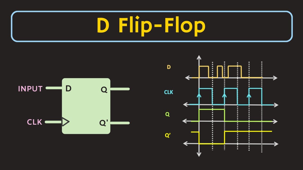
D Flip-Flop Explained | Truth Table and Excitation Table of D Flip-Flop
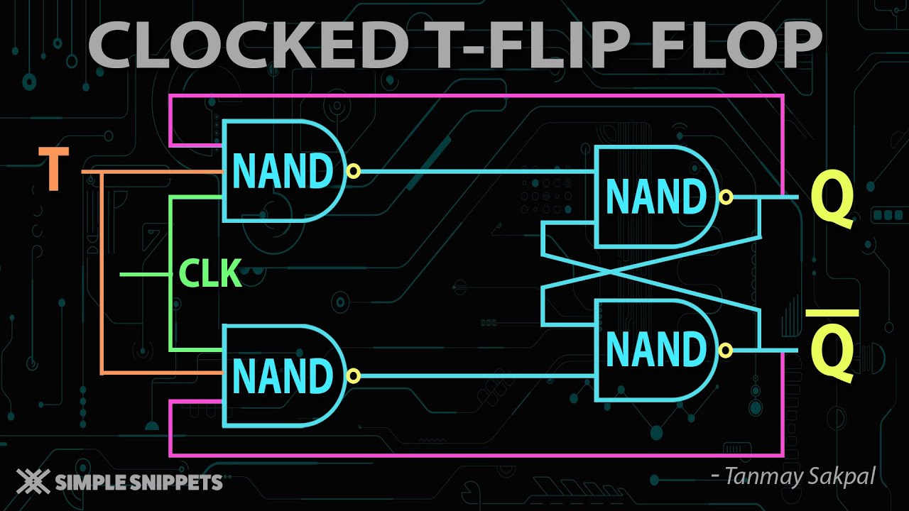
Clocked T Flip Flop using NAND Gates with Truth Table and Circuit Diagram

Clocked SR Flip Flop using NAND Gates with Truth Table and Circuit Diagram

SR Flip Flop to JK Flip Flop Conversion
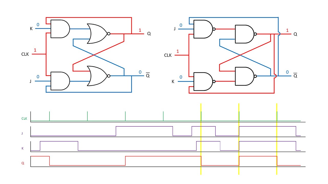
Latches and Flip-Flops 6 - The JK Flip Flop

SR Latch and Gated SR Latch Explained | SR Latch using NOR gates and NAND gates
5.0 / 5 (0 votes)
