Electrical Review - PLC Basics Part 1
Summary
TLDRThis video introduces the basics of electrical schematics, focusing on discrete circuits, their components, and their evolution into programmable logic controllers (PLCs). It explains how simple household circuits work, introduces relays to replace manual switches, and describes the complexity that grows as systems become automated. It highlights the shift from traditional relay logic to PLCs in the 1960s, offering a more efficient and safer alternative. The video emphasizes how modern PLC systems are easier to program and troubleshoot, making automation more accessible and manageable.
Takeaways
- 😀 Discrete circuits are fundamental in electrical systems, where the circuit is either on or off.
- 😀 A simple household light circuit is an example of a discrete circuit, with a power source, switch, and load.
- 😀 Power for these circuits can be 120 volts AC or 24 volts DC, with the latter being the newer industrial standard.
- 😀 A switch in a circuit can be manually operated or electronic, such as a photoelectric sensor.
- 😀 Loads in a circuit can include lights or motors, which are the devices powered by the circuit.
- 😀 Introducing electromechanical relays adds more control to a circuit, with coils that control contacts.
- 😀 Relays have normally open or normally closed contacts that change state when power is applied to the coil.
- 😀 Replacing manually operated switches with relays allows for safer control voltages while switching larger power circuits.
- 😀 Combining multiple circuits with relays marks the start of an automation system, but increases system complexity.
- 😀 In traditional relay logic systems, the wiring complexity can make diagnosis and troubleshooting difficult.
- 😀 In the late 1960s, General Motors sought a programmable system to replace complex relay panels, leading to the development of PLCs with ladder logic programming.
Q & A
What is a discrete circuit?
-A discrete circuit is a simple electrical circuit that operates in an 'on' or 'off' state. It's used for controlling devices like lights or motors in basic systems.
How does the power flow in a simple household light circuit?
-In a basic household light circuit, power is supplied from a panel breaker, and a switch controls the flow of electricity to turn the light on or off.
What is the typical voltage used in newer industrial circuits?
-In newer industrial systems, the standard voltage for circuits is typically 24 volts DC, as opposed to the older 120 volts AC.
What are the components of an electromechanical relay?
-An electromechanical relay consists of two main components: a coil and a contact. When the coil is energized, the contact closes, allowing power to pass through the device.
What is the difference between normally open and normally closed relay contacts?
-Normally open relay contacts close when power is applied to the coil, while normally closed contacts open when power is supplied to the coil.
Why are relays used in circuits instead of manual switches?
-Relays are used in circuits because they provide a safer, automated control of the power flow, allowing for switching high-power circuits using low-voltage control signals.
How does a relay improve a simple circuit?
-By replacing a manual switch, a relay allows for automatic control of power through its contacts, enabling more complex automation with minimal manual intervention.
What is a potential problem with traditional relay logic panels?
-Traditional relay logic panels can become very complex and difficult to troubleshoot as the system grows, making it challenging to diagnose issues.
How did the introduction of PLCs solve issues with traditional relay logic?
-In the late 1960s, General Motors requested a new system to replace complex relay panels. Programmable Logic Controllers (PLCs) emerged, simplifying systems and improving troubleshooting through their programmable nature.
What is ladder logic, and how is it related to PLCs?
-Ladder logic is a programming language that resembles electrical schematics, using contacts and coils, and is used in PLCs to control automation systems in a way similar to the relay logic but with greater flexibility and simplicity.
Outlines

هذا القسم متوفر فقط للمشتركين. يرجى الترقية للوصول إلى هذه الميزة.
قم بالترقية الآنMindmap

هذا القسم متوفر فقط للمشتركين. يرجى الترقية للوصول إلى هذه الميزة.
قم بالترقية الآنKeywords

هذا القسم متوفر فقط للمشتركين. يرجى الترقية للوصول إلى هذه الميزة.
قم بالترقية الآنHighlights

هذا القسم متوفر فقط للمشتركين. يرجى الترقية للوصول إلى هذه الميزة.
قم بالترقية الآنTranscripts

هذا القسم متوفر فقط للمشتركين. يرجى الترقية للوصول إلى هذه الميزة.
قم بالترقية الآنتصفح المزيد من مقاطع الفيديو ذات الصلة
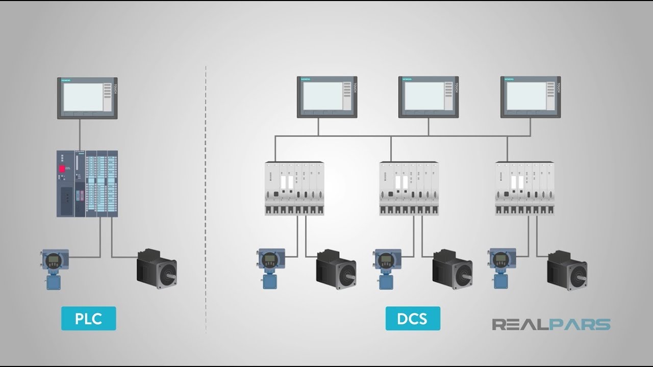
What is the Difference Between PLC and DCS?
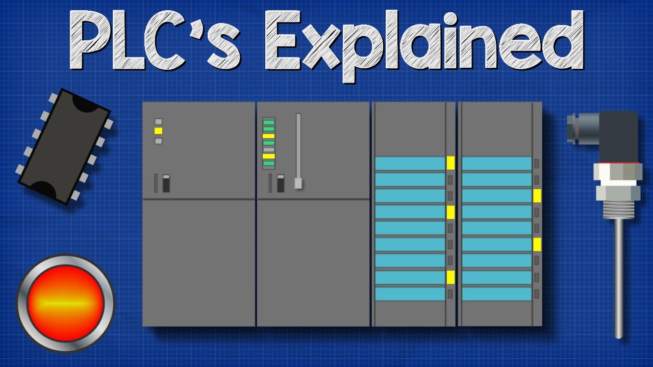
Programable Logic Controller Basics Explained - automation engineering

Ladder Logic Diagrams for PLCs | Industrial Automation
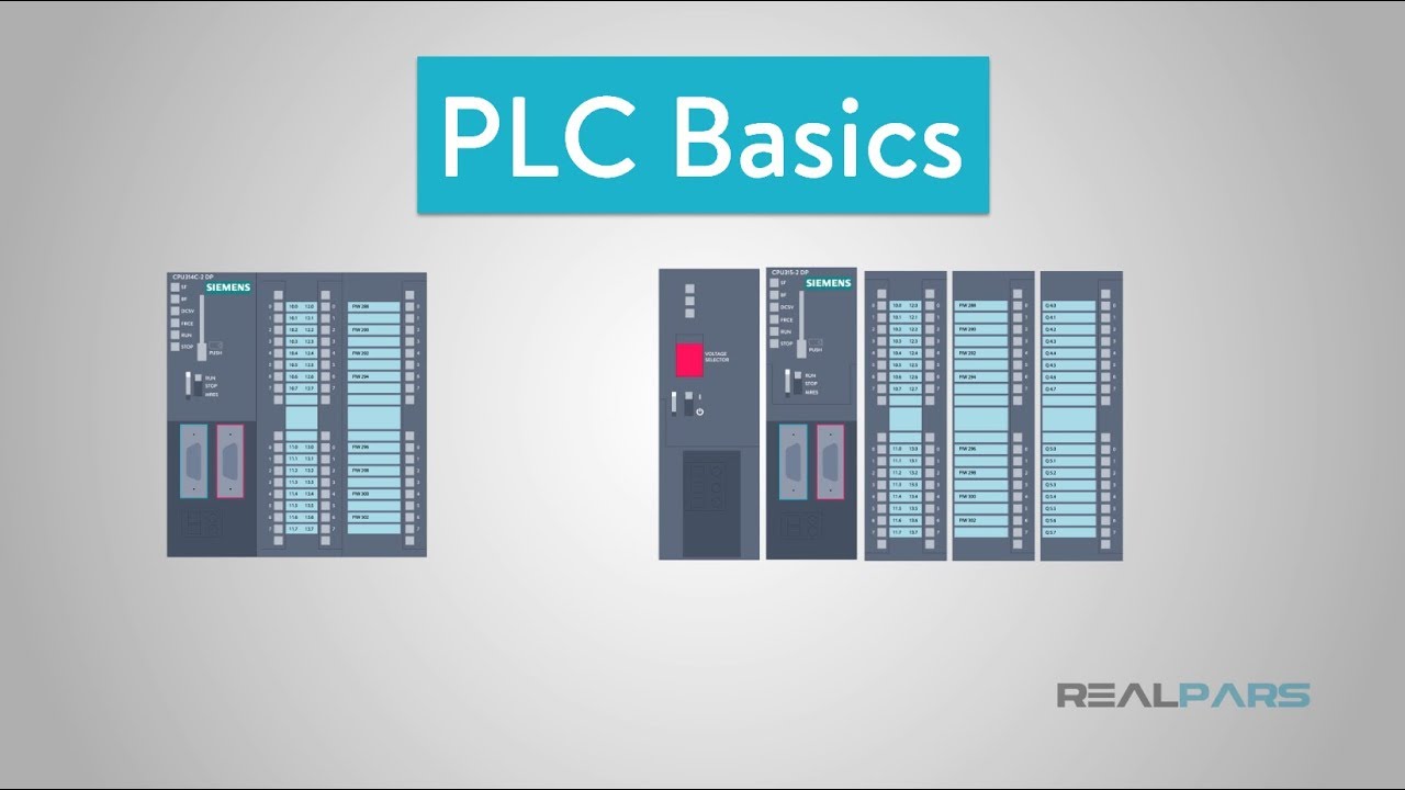
PLC Basics | Programmable Logic Controller
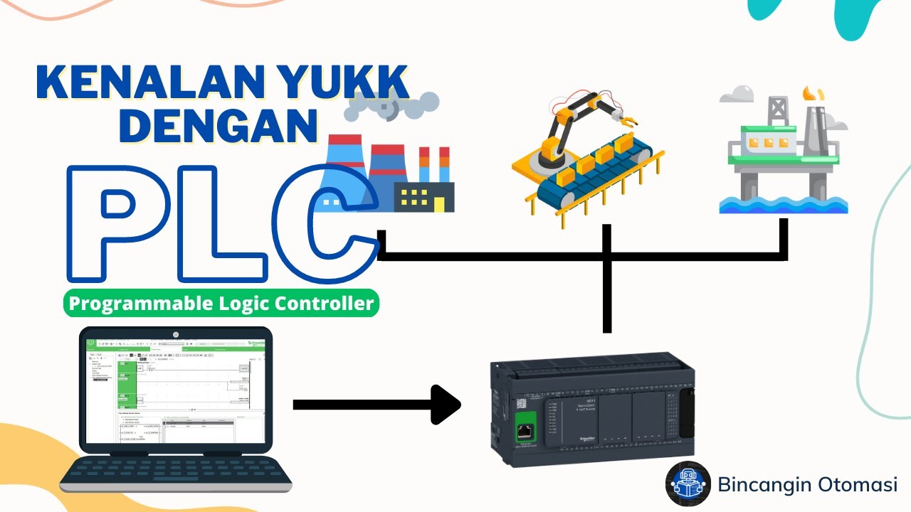
Belajar PLC | Pengenalan Programmable Logic Controller #1
1. Berkenalan Dengan Kerja Perangkat Kontrol PLC
5.0 / 5 (0 votes)
