Making Traffic Lights with Arduino Uno - Beginner Level (algorithm, coding, circuit design)
Summary
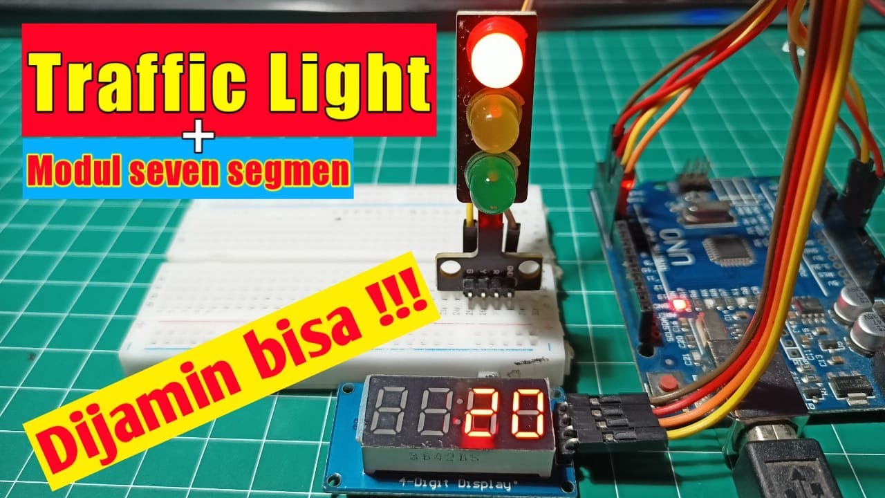
TLDRIn this instructional video, the host guides viewers through building a traffic light system using an Arduino kit. The project involves programming LEDs to mimic a traffic light sequence: red for 3 seconds, yellow for 1 second, followed by green for 3 seconds and a green light blink pattern. The video outlines the components needed, including LEDs, resistors, jumper wires, a breadboard, and an Arduino Uno. The host demonstrates the setup and coding process, encouraging viewers to subscribe for more educational content.
Takeaways
- 😀 The video is a tutorial on how to create a traffic light using an Arduino kit.
- 🔧 The presenter has ordered an Arduino kit, which includes a jacket and a simple traffic light project.
- 📹 The audience is encouraged to subscribe to the channel for more similar content.
- 🚦 The project involves creating a traffic light with red, yellow, and green LEDs following a specific algorithm.
- ⏱ The traffic light sequence includes red for 3 seconds, yellow for 1 second, both off, green for 3 seconds, and a green light blink for 0.5 seconds three times.
- 🔌 The components required for the project are three LEDs, jumper wires, 100-ohm resistors, a breadboard, and an Arduino Uno microcontroller.
- 🔩 The LEDs are connected to the breadboard with the anode on the right side and resistors to limit the current.
- 🔋 The power supply is set up with a 4-cell unit, each cell providing 1.5 volts.
- 📝 The Arduino code involves setting digital pins 8, 10, and 12 as outputs and controlling the LEDs according to the traffic light algorithm.
- 💻 The presenter demonstrates the code compilation and upload process to the Arduino board.
- 🎥 The final demonstration shows the traffic light functioning as expected, with the LEDs lighting up in sequence and blinking as programmed.
Q & A
What is the main project discussed in the video?
-The main project discussed in the video is creating a traffic light using an Arduino kit.
What are the colors of the LEDs used in the traffic light project?
-The colors of the LEDs used in the project are red, yellow, and green.
How long does the red light stay on according to the algorithm?
-According to the algorithm, the red light stays on for 3 seconds.
What is the duration for which the yellow light is kept on?
-The yellow light is kept on for 1 second.
How many times does the green light blink, and for how long each time?
-The green light blinks three times, each for half a second.
What are the components required for the traffic light project?
-The components required for the project are three LEDs, jumper wires, 100 ohm resistors, a breadboard, and an Arduino Uno microcontroller.
Which pins on the Arduino Uno are used for the red, yellow, and green LEDs?
-The pins used for the red, yellow, and green LEDs are 8, 10, and 12 respectively.
What is the purpose of the resistors in the circuit?
-The resistors are used to limit the current flowing through the LEDs, preventing them from drawing too much power and getting damaged.
How does the video describe the process of coding for the traffic light project?
-The video describes the coding process by explaining the use of the 'setup' and 'loop' functions, digital write commands for the LEDs, and the timing for each light state.
What is the final step shown in the video after uploading the code?
-The final step shown in the video is resetting the Arduino and observing the traffic light functioning as per the programmed algorithm.
How does the video encourage viewers to engage with the content?
-The video encourages viewers to subscribe to the channel, like the video, and leave comments for further interaction.
Outlines

هذا القسم متوفر فقط للمشتركين. يرجى الترقية للوصول إلى هذه الميزة.
قم بالترقية الآنMindmap

هذا القسم متوفر فقط للمشتركين. يرجى الترقية للوصول إلى هذه الميزة.
قم بالترقية الآنKeywords

هذا القسم متوفر فقط للمشتركين. يرجى الترقية للوصول إلى هذه الميزة.
قم بالترقية الآنHighlights

هذا القسم متوفر فقط للمشتركين. يرجى الترقية للوصول إلى هذه الميزة.
قم بالترقية الآنTranscripts

هذا القسم متوفر فقط للمشتركين. يرجى الترقية للوصول إلى هذه الميزة.
قم بالترقية الآنتصفح المزيد من مقاطع الفيديو ذات الصلة

[CUEE Camp 2nd] Part 2 : Condition and Loop
Simulasi Lampu Lalu Lintas - Arduino

Simulasi Lampu Lalu Lintas Menggunakan Arduino UNO di Wokwi

INTEGRATION OF SENSOR AND ACTUATORS WITH ARDUINO-I
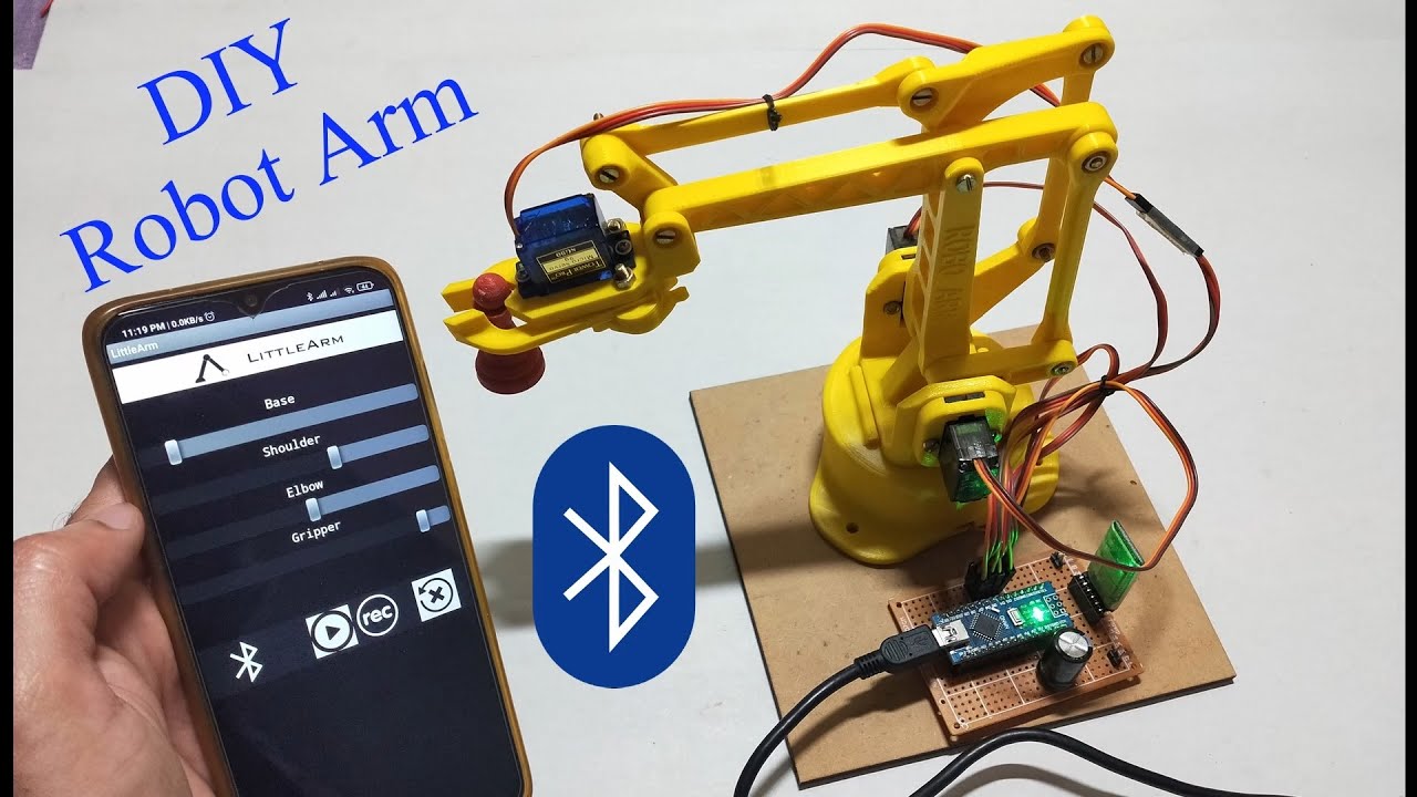
DIY | Smartphone (Bluetooth) controlled Robot Arm using Arduino | HC-05
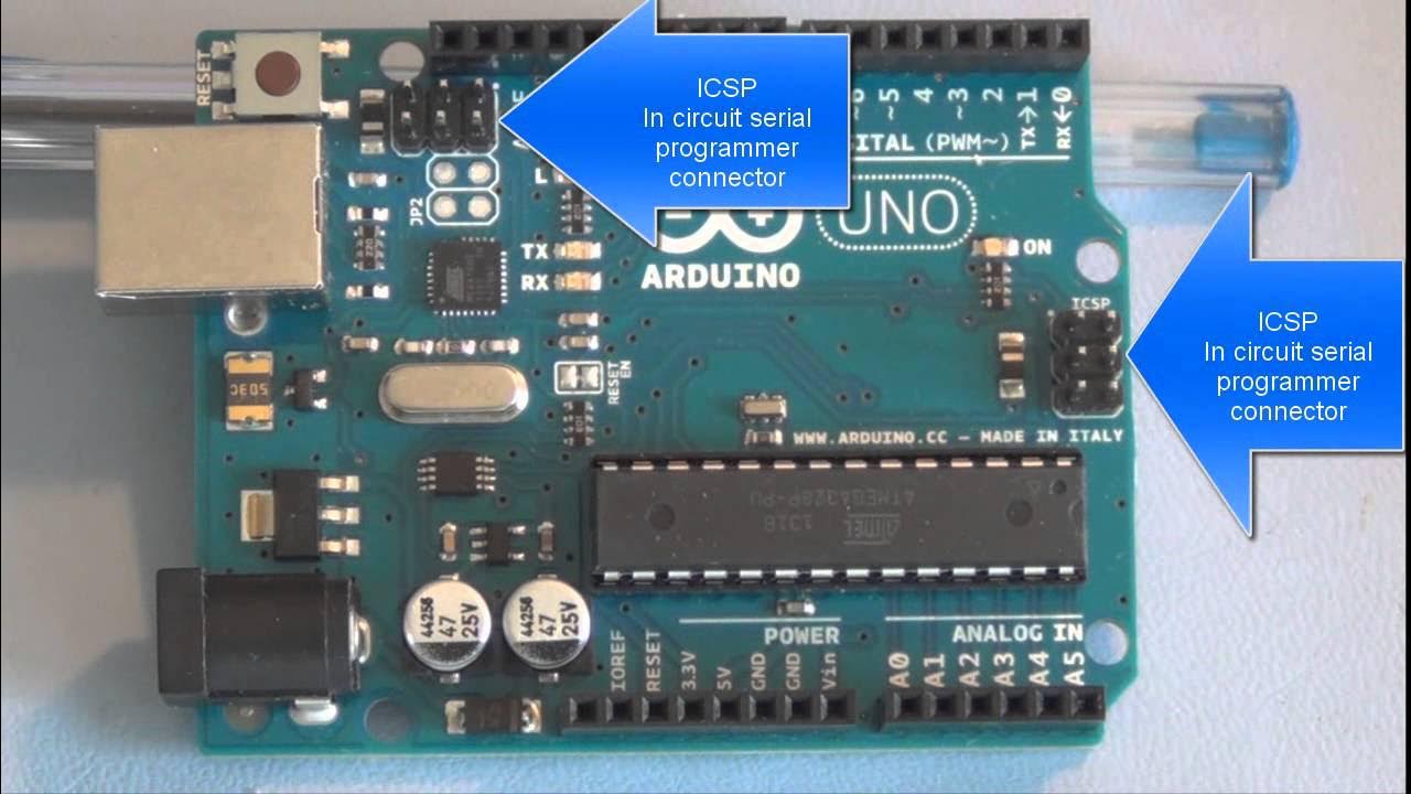
Arduino Uno tutorial Basic microcontroller overview
5.0 / 5 (0 votes)
