Membaca dan Mengukur dengan Osiloskop
Summary
TLDRIn this tutorial, the presenter demonstrates how to use an oscilloscope to measure and read signals from an inverting amplifier circuit. The video covers key steps like setting up the circuit, adjusting oscilloscope settings, and interpreting the voltage and frequency readings. The presenter walks through calculating the output voltage, comparing theoretical results with actual measurements, and troubleshooting potential discrepancies. The tutorial emphasizes understanding signal properties, adjusting oscilloscope controls, and applying formulas to predict voltage changes. It concludes by encouraging viewers to experiment with similar circuits like non-inverting amplifiers for further practice.
Takeaways
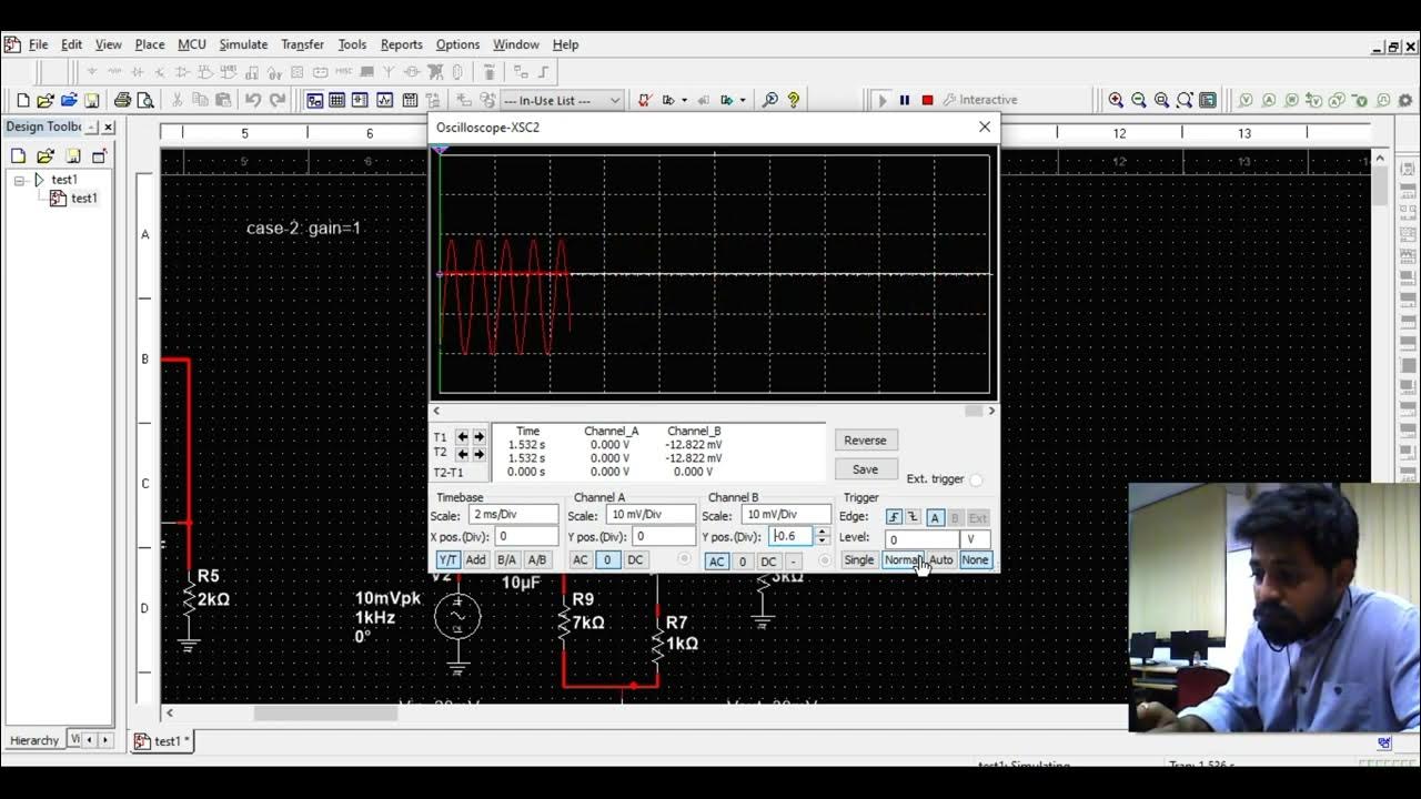
- 😀 Set up the oscilloscope by connecting Channel A to the output and Channel B to the input of the inverting amplifier circuit.
- 😀 Ensure the oscilloscope channels are set to DC mode, as the signal uses DC voltage.
- 😀 Adjust the signal generator's settings to get a clear, readable signal on the oscilloscope.
- 😀 Use the oscilloscope's grid system to measure the input and output voltages by counting the grid boxes.
- 😀 Measure the input voltage by observing how many grid boxes the signal spans on Channel B.
- 😀 To calculate the output voltage, multiply the number of grid boxes by the known voltage per box.
- 😀 For an inverting amplifier, expect the output voltage to be inverted (negative) compared to the input voltage.
- 😀 Use the formula for an inverting amplifier to predict the output voltage: V_out = - (R_f / R_in) × V_in.
- 😀 Check the real-world output voltage using a voltmeter and compare it with the calculated value.
- 😀 Note that there may be small discrepancies between oscilloscope readings and calculated results due to component tolerances and practical limitations.
- 😀 Experiment with both inverting and non-inverting amplifier circuits to fully understand oscilloscope readings and measurements.
Q & A
What is the main topic of the tutorial?
-The main topic of the tutorial is how to measure and read signals using an oscilloscope, specifically in an inverting amplifier circuit.
What is the purpose of the inverting amplifier circuit used in the tutorial?
-The inverting amplifier circuit is used to demonstrate how an oscilloscope can measure and display the amplified output signal, helping to understand voltage gain and signal inversion.
Which oscilloscope channels are used in the setup?
-In the setup, Channel A is used for the output signal, and Channel B is used for the input signal of the inverting amplifier.
How should the oscilloscope channels be set up before starting the measurement?
-The oscilloscope channels that are not in use (Channel C) should be turned off, and Channels A and B should be set to DC coupling mode to measure the DC voltage of the signals.
Why is it important to adjust the level of the signal in the oscilloscope?
-Adjusting the signal level is important to ensure that the signal is clearly visible on the oscilloscope screen, making it easier to measure and analyze the waveform.
How do you calculate the input and output voltages from the oscilloscope display?
-To calculate the input and output voltages, you multiply the voltage per division (V/div) by the number of divisions the waveform spans. For example, if the waveform spans two divisions, and each division represents 1 volt, the total voltage would be 2 volts.
What is the significance of the formula used for the inverting amplifier circuit?
-The formula used, V_out = - (R_f / R_in) * V_in, helps calculate the output voltage (V_out) based on the input voltage (V_in) and the ratio of the feedback resistor (R_f) to the input resistor (R_in). This shows how the signal is inverted and amplified.
What is the relationship between the input and output voltages in the inverting amplifier circuit?
-In the inverting amplifier circuit, the output voltage is inverted and amplified by a factor determined by the ratio of the feedback resistor (R_f) to the input resistor (R_in). For example, if the ratio is 1.74, the output voltage will be approximately 1.74 times the input voltage but inverted in polarity.
Why might there be a slight difference between the theoretical voltage and the measured voltage?
-The slight difference between the theoretical and measured voltages can be due to factors like component tolerances, measurement errors, and variations in the oscilloscope settings or signal generation.
What is the purpose of using a DC voltmeter in the tutorial?
-The DC voltmeter is used to directly measure the input and output voltages of the inverting amplifier circuit, providing a straightforward reading of the voltage levels.
Outlines

هذا القسم متوفر فقط للمشتركين. يرجى الترقية للوصول إلى هذه الميزة.
قم بالترقية الآنMindmap

هذا القسم متوفر فقط للمشتركين. يرجى الترقية للوصول إلى هذه الميزة.
قم بالترقية الآنKeywords

هذا القسم متوفر فقط للمشتركين. يرجى الترقية للوصول إلى هذه الميزة.
قم بالترقية الآنHighlights

هذا القسم متوفر فقط للمشتركين. يرجى الترقية للوصول إلى هذه الميزة.
قم بالترقية الآنTranscripts

هذا القسم متوفر فقط للمشتركين. يرجى الترقية للوصول إلى هذه الميزة.
قم بالترقية الآنتصفح المزيد من مقاطع الفيديو ذات الصلة
Multisim Tutorials --2: CE amplifier simulation part 1

6a Praktek Cara Mengkalibrasi dan Menggunakan Osiloskop untuk Mengukur Tegangan dan Frekuensi

Active Low Pass Filter - EXPERIMENT

Pengukuran Besaran Listrik - Oscilloscope
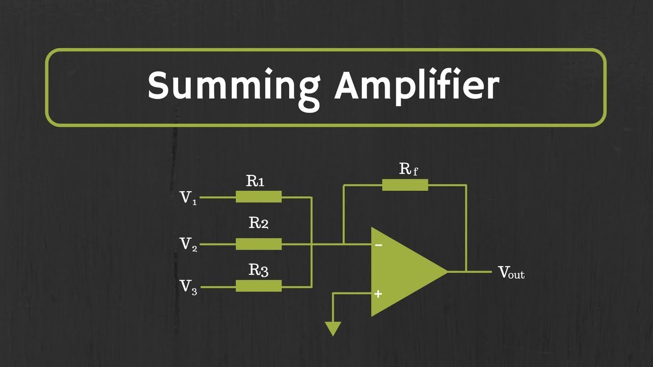
Op-Amp: Summing Amplifier (Inverting and Non-Inverting Summing Amplifiers)
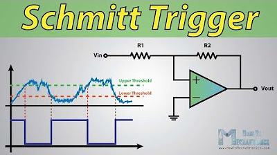
What Is Schmitt Trigger and How It Works
5.0 / 5 (0 votes)
