Dasar Teknik Elektro - Seri Pembagi Tegangan
Summary
TLDRThis video tutorial covers the concept of voltage dividers, focusing on how resistors in series divide voltage in a circuit. It explains both theoretical calculations and practical measurements with real circuits. Through several examples, the video demonstrates how to calculate output voltage using Ohm's Law and resistor values, along with hands-on experiments that validate the calculations. The tutorial emphasizes the importance of resistor selection to achieve desired voltage outputs and highlights the impact of adding loads to a voltage divider, showing how lower load resistance can cause significant voltage drops.
Takeaways
- 😀 The video introduces the concept of voltage divider circuits, explaining how resistors can divide voltage in an electrical circuit.
- 😀 The first example demonstrates how to calculate the total resistance of a series circuit and determine the current flowing through it using Ohm's Law.
- 😀 In the first example, the total resistance of the series circuit is 30 ohms, resulting in a current of 0.4 amps and a voltage drop of 8 volts across R2.
- 😀 Two methods are provided for calculating the output voltage across a resistor in a voltage divider, both yielding the same result of 8 volts.
- 😀 A hands-on experiment is shown, confirming that the theoretical calculations hold up in real-world practice, with measured voltages matching expectations.
- 😀 The second example focuses on designing a voltage divider to output 6 volts with a current of 60 mA, using two resistors of equal value.
- 😀 Using Ohm's Law, the required resistor values are calculated to be 100 ohms for both R1 and R2 to achieve the desired output of 6 volts.
- 😀 The second experiment demonstrates the setup with resistors of 100 ohms each and confirms that the output voltage is indeed 6 volts as calculated.
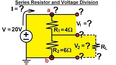
- 😀 The third example explores designing a voltage divider to output 12 volts with a 20-volt input, calculating the resistor values needed for a current of 50 mA.
- 😀 After calculating the total resistance of the circuit, the video demonstrates how to achieve the desired output voltage by selecting appropriate resistor values, resulting in R1 = 160 ohms and R2 = 240 ohms.
Q & A
What is a voltage divider and how is it demonstrated in the video?
-A voltage divider is a circuit that splits the voltage across two resistors connected in series. In the video, the concept is demonstrated with two resistors, R1 and R2, in series with a 12V battery. The voltage across R2 is calculated and verified through both theoretical formulas and practical experiments.
How is the total resistance calculated for resistors in series?
-For resistors in series, the total resistance (R_total) is the sum of individual resistances. In the example shown, R1 is 10 ohms and R2 is 20 ohms, so R_total = 10 + 20 = 30 ohms.
How is the current through the circuit calculated in the video?
-The current (I) is calculated using Ohm's law, which is V = I * R. Rearranging to solve for I, we get I = V / R. With a voltage of 12V and a total resistance of 30 ohms, the current is I = 12V / 30 ohms = 0.4A.
How is the voltage across R2 calculated in the video?
-The voltage across R2 is calculated using the formula V = I * R. With the current of 0.4A flowing through R2 (20 ohms), the voltage is V = 0.4A * 20 ohms = 8V.
What is the second method used to calculate the voltage across R2?
-The second method uses the voltage divider formula: V_output = V_source * R2 / (R1 + R2). Substituting the values, V_output = 12V * 20 / (10 + 20) = 8V.
What happens when the practical setup is tested with resistors of 10 ohms and 20 ohms?
-When the practical setup is tested, the output voltage measured is 7.3V, which is slightly lower than the calculated 8V. This discrepancy could be due to real-world factors such as component tolerances.
How does the video explain designing a voltage divider with specific output voltage and current?
-The video explains that to design a voltage divider for a specific output voltage, such as 6V, and a current of 60mA, you first calculate the total resistance needed (R_total = V / I). Then, R1 and R2 are chosen such that their sum equals the calculated total resistance, and their ratio ensures the desired output voltage.
What are the resistor values chosen for the second practical experiment to output 6V?
-For the second experiment, to get a 6V output with a 12V input and a 60mA current, both resistors R1 and R2 are chosen to be 100 ohms each, as this configuration splits the voltage evenly.
What is the effect of adding a load resistor in the voltage divider circuit?
-Adding a load resistor to the circuit reduces the output voltage. The video demonstrates this by adding a 1000-ohm load resistor to a 20V circuit, which causes the output voltage to drop from 10V to 9.52V.
How does the load resistor impact the voltage output when it has a lower resistance?
-When the load resistor has a lower resistance, such as 10 ohms, the output voltage drops significantly. In the video, the output voltage drops from 10V to 1.67V when a 10-ohm load is added to the circuit.
Outlines

هذا القسم متوفر فقط للمشتركين. يرجى الترقية للوصول إلى هذه الميزة.
قم بالترقية الآنMindmap

هذا القسم متوفر فقط للمشتركين. يرجى الترقية للوصول إلى هذه الميزة.
قم بالترقية الآنKeywords

هذا القسم متوفر فقط للمشتركين. يرجى الترقية للوصول إلى هذه الميزة.
قم بالترقية الآنHighlights

هذا القسم متوفر فقط للمشتركين. يرجى الترقية للوصول إلى هذه الميزة.
قم بالترقية الآنTranscripts

هذا القسم متوفر فقط للمشتركين. يرجى الترقية للوصول إلى هذه الميزة.
قم بالترقية الآنتصفح المزيد من مقاطع الفيديو ذات الصلة


5.0 / 5 (0 votes)
