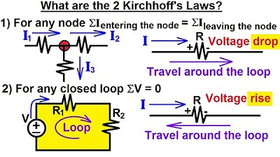
Electrical Engineering: Basic Laws (11 of 31) Kirchhoff's Laws: A Medium Example 2
Summary
TLDRThis video demonstrates how to apply Kirchhoff's laws to solve a two-loop circuit with a voltage source and three resistors. It illustrates using Kirchhoff's current and voltage laws to derive three equations, allowing calculation of currents through all resistors. The analysis starts by assuming current directions and applying Kirchhoff's first law at a node. Then, Kirchhoff's second law is applied to each loop to derive voltage equations. The resulting equations are solved simultaneously to find the currents. Although other methods may be easier, this approach effectively illustrates Kirchhoff's laws in action.
Takeaways
- 🔋 The circuit involves a two-loop configuration with a voltage source and three resistors.
- 🌀 Kirchoff's Laws are used to solve for the currents in all three resistors, providing a clear example of applying these rules.
- 🔄 The first assumption involves the direction of current flow through the three resistors, and if the assumptions are incorrect, negative values indicate the actual direction.
- 📏 Kirchoff's First Law (Current Law) states that the sum of currents entering a node must equal the sum of currents leaving that node.
- 🔁 A node is identified where current i1 enters, and currents i2 and i3 leave, leading to the first equation: i1 = i2 + i3.
- 🔋 Kirchoff's Second Law (Voltage Law) is applied to both loops, stating that the sum of voltage drops and rises around a loop must equal zero.
- 🔄 Loop 1 results in a voltage rise across the battery and voltage drops across the resistors, leading to the second equation.
- 🔁 Loop 2 also gives another equation, involving voltage rises and drops across the resistors, forming the third equation.
- 🔧 The system of equations is solved by substitution and elimination, ultimately calculating i2 and i3.
- 💡 The solution shows that i1 = 3A, i2 = 2A, and i3 = 1A, validating the node current splits and direction assumptions.
Q & A
What is the purpose of using Kirchhoff's laws in this circuit analysis?
-Kirchhoff's laws are used to solve for the current flowing through all three resistors by creating equations based on the sum of currents at a node and the sum of voltage drops in loops. This method is illustrated to show how to solve a circuit that could also be solved using simpler methods, like finding equivalent resistance.
What are Kirchhoff's two laws mentioned in the script?
-The first law (Kirchhoff's Current Law) states that the sum of currents entering a node must equal the sum of currents leaving the node. The second law (Kirchhoff's Voltage Law) states that the sum of voltage rises and drops around any closed loop must add up to zero.
How are the current directions assumed in this circuit?
-The current directions are assumed arbitrarily for each resistor. If the actual direction differs, the result will be a negative value, indicating that the assumed direction was incorrect. However, this won't affect the solution.
What is the first equation derived from Kirchhoff's Current Law (KCL)?
-The first equation derived from KCL is i1 = i2 + i3, where i1 is the current entering the node, and i2 and i3 are the currents leaving the node.
How are the two loops defined in the circuit?
-The two loops are defined by tracing a path around the circuit. Loop 1 is traced clockwise around the first part of the circuit, and Loop 2 is traced counterclockwise around the second part of the circuit. The sum of voltages in each loop must equal zero according to Kirchhoff's Voltage Law.
What is the second equation derived from Loop 1?
-The second equation from Loop 1 is 30 - 8i1 - 3i2 = 0. This represents the voltage rise from the 30V source and the voltage drops across the 8-ohm and 3-ohm resistors in the direction of the current.
What is the third equation derived from Loop 2?
-The third equation from Loop 2 is 3i2 - 6i3 = 0. This represents the voltage rise across the 3-ohm resistor (going against the current) and the voltage drop across the 6-ohm resistor (in the direction of the current).
How are the three equations solved simultaneously?
-To solve the system, i1 is substituted into the second equation to get two equations with i2 and i3. Then, the equations are manipulated to eliminate one variable, allowing for the solution of i2 and i3. Finally, i1 is found using the first equation (i1 = i2 + i3).
What are the final values of the currents i1, i2, and i3?
-The final values are i1 = 3A, i2 = 2A, and i3 = 1A. These values satisfy both Kirchhoff’s Current Law and Voltage Law, meaning the solution is correct.
What would happen if the directions of the currents were assumed incorrectly?
-If the current directions were assumed incorrectly, the final solution would give a negative value for the current, indicating that the actual current flows in the opposite direction to what was assumed. However, this doesn't affect the validity of the results.
Outlines

هذا القسم متوفر فقط للمشتركين. يرجى الترقية للوصول إلى هذه الميزة.
قم بالترقية الآنMindmap

هذا القسم متوفر فقط للمشتركين. يرجى الترقية للوصول إلى هذه الميزة.
قم بالترقية الآنKeywords

هذا القسم متوفر فقط للمشتركين. يرجى الترقية للوصول إلى هذه الميزة.
قم بالترقية الآنHighlights

هذا القسم متوفر فقط للمشتركين. يرجى الترقية للوصول إلى هذه الميزة.
قم بالترقية الآنTranscripts

هذا القسم متوفر فقط للمشتركين. يرجى الترقية للوصول إلى هذه الميزة.
قم بالترقية الآنتصفح المزيد من مقاطع الفيديو ذات الصلة
5.0 / 5 (0 votes)


