Arduino Self-Driving Car Lesson 3: Controlling Motor Speed

Science Buddies
1 Jun 202314:19

Summary

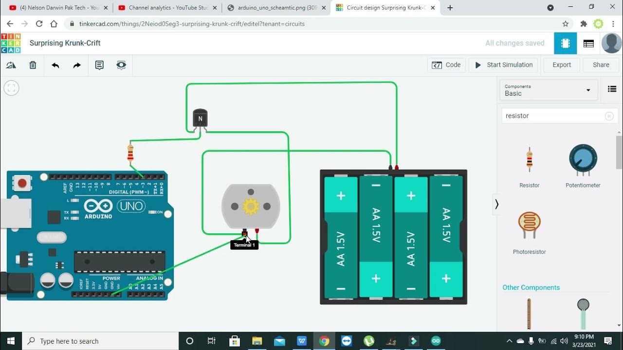
TLDRThis video teaches how to control the speed of a motor using an Arduino and pulse width modulation (PWM). Instead of running a motor at full speed or stopping, the video explains how to gradually ramp up and down the motor's speed. By manipulating the enable pin and using PWM pins, the speed can be adjusted to fine-tune the motor's performance, which is useful in robotic vehicles. The tutorial walks through wiring the circuit in Tinkercad, writing the code, and implementing the analog write command to control motor speed effectively.

Takeaways

  • 🔧 Learn how to control the speed of a motor, allowing for variable speeds instead of just stop-and-go.
  • 🔋 The motor's speed can ramp up and down gradually, not just switching between full speed and stop.
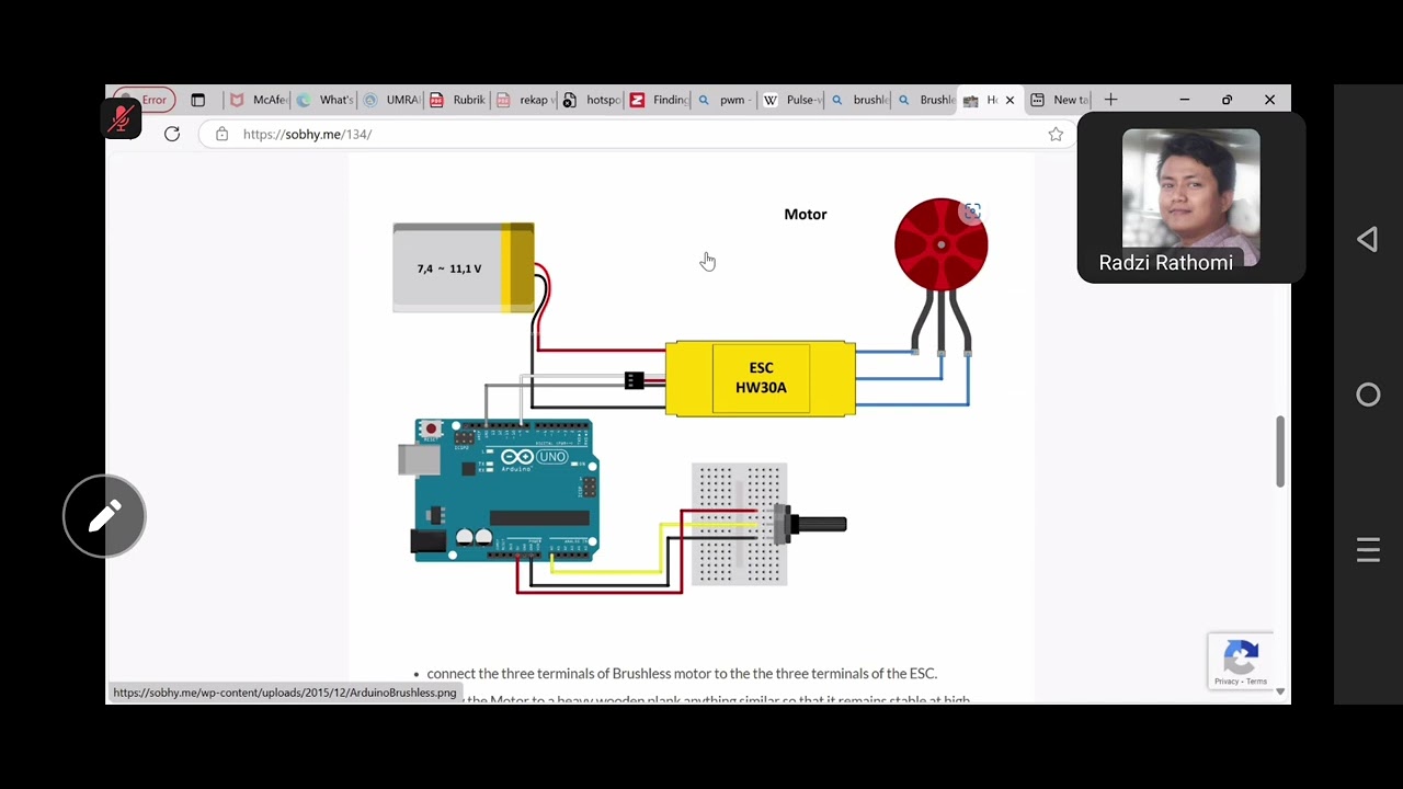
  • 🎮 Using PWM (pulse width modulation) through specific Arduino pins, you can control motor speed more precisely.
  • 🔀 Two Arduino pins control the motor’s direction, and now a third pin can manage speed by connecting to the enable pin.
  • ⚙️ PWM rapidly turns pins on and off to simulate different average voltages, creating the effect of variable speed.
  • 🖥️ The `analogWrite` command controls motor speed, taking values between 0 and 255 to represent different levels of speed.
  • 🔄 The script shows how to adjust motor speed independently of direction using the `analogWrite` command.
  • 🏎️ This method allows for fine-tuning in cases where the vehicle drifts off course, compensating for motor differences.
  • 🛠️ Modify your code to control both motors independently and experiment with different speed values to adjust performance.
  • 📐 By adding inputs to your functions, you can make the robot drive forward at varying speeds without rewriting code for each speed.

Q & A

  • What is the purpose of controlling the motor's speed in a robotic vehicle?

    -Controlling the motor's speed allows for smoother movement, helps the vehicle drive and turn at different speeds, and compensates for any drift if the vehicle tends to veer off course when moving straight.

  • What is pulse width modulation (PWM) and how does it help control motor speed?

    -PWM is a technique where the digital pins on the Arduino rapidly switch between high (5V) and low (0V). By adjusting how long the signal stays high or low, PWM can mimic different voltage levels, effectively controlling the motor's speed.

  • Why can't the Arduino provide true analog output for motor speed control?

    -The Arduino lacks a true analog output capability, so it uses PWM to simulate analog signals by rapidly turning the digital pins on and off, creating an average voltage that controls motor speed.

  • How can you use the analogWrite command to control motor speed?

    -The analogWrite command accepts a value between 0 and 255, where 0 is no speed (motor off) and 255 is full speed. By specifying different values, you can control how fast the motor spins.

  • Why is it important to use PWM pins for motor speed control?

    -PWM pins are essential because they are the only pins capable of generating the PWM signal required to simulate analog output, which is necessary for controlling the motor’s speed.

  • What happens if the PWM value is set too low, for example, 10?

    -At very low PWM values like 10, the motor might not spin because the voltage is too low to overcome internal friction. The motor may make a whining noise but will not move.

  • How can you fix a robotic vehicle that drifts to one side while driving straight?

    -You can use the analogWrite command to adjust the speed of the motors independently. For example, if the vehicle drifts to the right, you can slow down the left motor until the vehicle drives straight.

  • How does adding speed control make the drive forward function more flexible?

    -By adding speed inputs to the drive forward function, you can control how fast the vehicle moves without having to write separate functions for different speeds. This makes the function more versatile for different scenarios.

  • What additional components are needed to make the vehicle react to its environment?

    -To make the vehicle react to its environment like a real autonomous car, you need to add sensors that can detect obstacles and other elements in the surroundings. These will be covered in the next steps of the project.

  • Why is it beneficial to use different speeds for the motors when turning the vehicle?

    -Using different speeds for the motors allows for smoother, gradual turns, as opposed to abrupt changes in direction. This gives more precise control over the vehicle's movements.

Outlines

00:00

🔧 Introduction to Motor Speed Control

This paragraph introduces the concept of controlling motor speed using an Arduino. It highlights how, instead of just alternating between stopping and full speed, one can gradually ramp up and down motor speed. The focus is on practical applications such as making robotic vehicles drive and turn at different speeds to compensate for steering drift.

05:02

💡 Recap and PWM Introduction

Here, the video transitions into a recap of how motors were previously controlled via two Arduino pins, which managed the motor's direction. The concept of pulse width modulation (PWM) is introduced, explaining how this technique allows for speed control by adjusting the duty cycle of the signal sent to the motor's enable pin. This method fakes an analog signal and can vary motor speed from 0 to full speed.

10:03

📐 Adjusting Motor Speed with Code

The focus of this paragraph is the implementation of PWM in code. The 'analogWrite' function is discussed in detail, allowing the motor to run at different speeds by specifying a value between 0 and 255. The use of pin 6 for speed control and how changing the analogWrite value affects motor speed in simulations is demonstrated.

🚗 Testing Speed Control and Debugging

The paragraph discusses the results of setting different PWM values (255, 128, and 10) for motor speed. The video shows that very low values may not overcome motor friction, preventing it from spinning at low speeds. It explains that while high-speed control is effective, very low-speed control might not be reliable due to friction. The example also demonstrates how these PWM adjustments affect the vehicle's movement, particularly when trying to drive straight.

🔄 Independent Control of Both Motors

The video now explains how to control the speed of both motors independently, allowing for more precise control of the vehicle's movement. It introduces the concept of tweaking the motor speeds to correct drifting during forward movement. The author provides step-by-step guidance on how to modify the code to handle two motors using PWM pins.

🛠️ Enhancing Flexibility with Speed Inputs

The final paragraph introduces more advanced programming techniques by adding flexibility to the 'drive forward' function. By adding speed input arguments for each motor, the function can now control forward movement at different speeds without needing separate functions. This opens up more possibilities for creating dynamic and adaptable movement in the robot. It sets the stage for adding sensors for real-time environmental interaction.

Mindmap

Keywords

💡Motor Speed Control

Motor speed control refers to the ability to adjust the speed of a motor in a circuit. In the video, it is highlighted as the main goal, showing how to manipulate motor speed using pulse width modulation (PWM) to allow different levels of speed rather than just turning the motor on or off. This concept is essential for tasks like steering a robotic vehicle accurately.

💡Pulse Width Modulation (PWM)

Pulse Width Modulation (PWM) is a technique used to simulate varying voltages by switching a digital signal on and off at high speeds. The video uses PWM to control the motor's speed by adjusting how long the signal stays high versus low, creating the effect of different voltages to slow down or speed up the motor. This is a central concept for achieving precise motor control without analog outputs.

💡Arduino

Arduino is a microcontroller platform used to build electronic projects. In the video, the Arduino is programmed to control the speed and direction of motors in a robotic vehicle. The viewer is shown how to connect the motor to the Arduino and use its pins for controlling both direction and speed, making it a fundamental component of the project.

💡H-Bridge

An H-Bridge is an electronic circuit that allows a motor to be driven in both directions. The video mentions the use of an H-Bridge to control the motor's direction by toggling the high and low signals on different pins. This is crucial for tasks like steering a robotic vehicle, enabling it to move forward, backward, and turn.

💡Enable Pin

The enable pin is a control pin on the H-Bridge that determines whether the motor is active or not. In the video, the enable pin is initially connected directly to 5 volts, making the motor run at full speed. Later, it is connected to a PWM-enabled Arduino pin to control the motor's speed, giving the user more flexibility in speed adjustment.

💡Digital Write

Digital write is a command in Arduino programming that sets a digital pin to either HIGH (5 volts) or LOW (0 volts). In the video, it is used to control the motor's direction by toggling the pins high and low. However, this command alone cannot control the motor speed, which is where analog write and PWM come into play.

💡Analog Write

Analog write is a command in Arduino that mimics an analog signal by rapidly switching a digital pin between high and low states, simulating different voltages. In the video, analog write is used to control the motor's speed by sending varying PWM signals to the enable pin, allowing the motor to run at speeds between 0 and full speed.

💡Robot Steering

Robot steering refers to controlling the direction of a robotic vehicle by adjusting the speed of its motors. The video explains how uneven motor speeds can cause the vehicle to drift and how PWM can be used to correct this by controlling the speed of each wheel independently, ensuring the vehicle moves straight or makes smooth turns.

💡Rotations Per Minute (RPM)

Rotations Per Minute (RPM) is a measure of how many times the motor's shaft spins in a minute. In the video, RPM is used as a way to monitor the motor's speed during simulation. For example, when the PWM value is reduced, the motor’s RPM decreases, allowing the viewer to visually and numerically observe the changes in motor speed.

💡Drive Forward Function

The drive forward function is a custom function in the Arduino code that controls the robot's movement by setting both motors to move the vehicle forward. In the video, the code is modified to include speed control for each motor, allowing the vehicle to move straight or at different speeds depending on the values passed into the function.

Highlights

Learn how to control motor speed to make it rotate at different speeds rather than just alternating between stopping and full speed.

Explanation of using the enable pin on the H-bridge to control motor speed through the Arduino instead of connecting it directly to 5 volts.

Introduction to pulse width modulation (PWM) as a method for simulating analog output to control motor speed using digital pins.

Using the analogWrite command to control the motor's speed by adjusting the duration of high and low signals on the PWM pin.

Demonstration of changing motor speeds by adjusting PWM values: 0-255, with 255 being full speed and lower values reducing the speed proportionally.

Controlling speed and direction independently for each motor, helping to correct issues like a vehicle drifting to one side.

Exploring the limits of motor speed control: very low PWM values (e.g., 10) may not overcome motor friction, leading to no movement.

Adjusting motor speeds to drive in a straight line, compensating for natural drift due to friction or motor imbalance.

Practical example of adjusting speeds to fix drifting issues, demonstrated by slowing one motor to align the vehicle's path.

Using PWM to intentionally create gradual turns or controlled vehicle maneuvers by setting different speeds for the left and right motors.

Incorporating speed control into existing functions like 'drive forward' by adding variable inputs for left and right motor speeds.

Highlighting flexibility in vehicle control by modifying existing drive functions to accept different speed values instead of creating separate functions.

Explaining the analogWrite command’s range of 0-255, based on an 8-bit number system, and its impact on motor speed.

Adapting speed control functions to maintain consistent motor directions while adjusting speeds independently.

Introduction to using sensors for vehicle navigation, which will allow the robot to respond to its environment like a real autonomous car.

Transcripts

play00:00

in this video you will learn how to

play00:02

control the speed of a motor so you can

play00:04

make it rotate at different speeds

play00:06

instead of just alternating between

play00:07

stopping and full speed you can see here

play00:10

I'm running a program that makes the

play00:11

motor speed ramp up and then ramp back

play00:13

down gradually instead of just going

play00:15

instantly to full speed I'm going to

play00:17

unplug the motor now so you can hear me

play00:19

a little better this will allow you to

play00:21

make your robotic vehicle drive and turn

play00:23

at different speeds and help you

play00:25

compensate for the steering if it tends

play00:27

to Drift Off to one side when you try to

play00:29

make it drive straight let's switch over

play00:31

to tinkercad and take a look at how we

play00:33

are going to wire and program the

play00:34

circuit to control the motor's speed now

play00:36

don't be intimidated by this circuit you

play00:38

should have it assembled from a previous

play00:40

video and we are only going to worry

play00:42

about one of the motors for now so you

play00:44

can ignore most of the connections over

play00:46

here on the left hand side of the H

play00:47

Bridge we're just going to look at the

play00:48

connections on this side for the most

play00:50

part so as a recap each motor is

play00:53

controlled by two pins on the Arduino

play00:55

that control the motor's direction if we

play00:58

set one of those pins High while the

play01:00

other pin is low it'll make the motor

play01:02

spin if we switch which pin is high and

play01:04

low it'll make the motor spin in the

play01:06

other direction and if we set both pins

play01:08

low the motor will stop

play01:09

what we did before though is there's

play01:11

this extra pin called the enable pin

play01:14

that we connected directly to 5 volts on

play01:17

the Arduino and that is always setting

play01:20

this pin high so the motor is always

play01:23

going to go full speed what we can do

play01:25

instead is remove this jumper wire and

play01:28

connect this enable pin to one of the

play01:31

arduino's pins that way we will have

play01:33

three pins controlling each motor two

play01:35

for the direction and one for the speed

play01:37

and to do that we need to connect to one

play01:40

of the Arduino pins with the little

play01:42

squiggly symbol or tilde next to it and

play01:45

those are the pins that can do pwm or

play01:48

pulse width modulation so before we use

play01:51

those pins let's talk a little bit about

play01:53

what that means here's what you have

play01:55

been doing so far with the arduino's

play01:57

pins you have been using the digital

play01:59

write command to set the digital pins

play02:01

either high or low high has a voltage of

play02:04

5 volts low has a voltage of zero volts

play02:07

but you cannot choose a voltage in

play02:09

between for example you can't set a PIN

play02:12

to two and a half volts to do that you

play02:15

need an analog signal or a signal that

play02:18

is continuously variable unlike digital

play02:20

signals which can only be high or low an

play02:23

analog signal can take on any value in

play02:26

between the minimum and the maximum so

play02:28

for example you could set an analog

play02:30

voltage to exactly two and a half volts

play02:33

the problem is that the Arduino does not

play02:35

have a true analog output however it can

play02:38

fake an analog output using the digital

play02:41

pins and something called pulse width

play02:44

modulation or very rapidly turning the

play02:47

digital pins on and off so for example

play02:49

you can imagine that if I very rapidly

play02:51

switch between 0 volts and 5 volts and I

play02:54

am low 50 of the time and high fifty

play02:57

percent of the time than my effective

play02:59

average voltage would be two and a half

play03:01

volts so you can do this using the

play03:04

analog write command you just have to

play03:06

remember that the analog right command

play03:07

is not outputting a true analog signal

play03:10

it is turning the pin on and off very

play03:12

quickly to kind a fake and intermediate

play03:15

analog voltage but this lets you do

play03:17

something like control the speed of a

play03:19

motor if you want the motor to spin

play03:20

roughly half speed then you want the

play03:22

signal to be high half of the time and

play03:24

low half of the time if you want it to

play03:26

spin faster then you want the signal to

play03:28

be high for longer than its low because

play03:30

this will give you a higher average

play03:32

voltage

play03:33

similarly if you want the motor to spin

play03:35

slower you want the signal to be low for

play03:37

longer than its high because this will

play03:39

give you a lower average voltage now

play03:42

this is a pretty Advanced concept so

play03:44

don't worry if you don't perfectly

play03:45

understand all of it next I'll show you

play03:47

how to implement this concept using the

play03:49

analog write command in code so going

play03:52

back to the Arduino remember that I said

play03:53

we need to use one of the pwm pins not

play03:57

all of the pins have pwm capabilities so

play04:00

we need to pick one with the squiggly

play04:02

symbol or tilde next to it I am going to

play04:04

choose pin 6 just because that's an open

play04:07

pwm pin and I'm going to run a jumper

play04:09

wire from there over to the enable pin

play04:12

on my H bridge and say I'm going to

play04:14

choose a different color I'm using blue

play04:16

for my direction control wires maybe I'm

play04:17

going to use green for my speed control

play04:19

wires now let's modify the code to use

play04:22

the analog right command to control the

play04:24

speed of this motor so here I have the

play04:27

program I wrote previously to steer an

play04:29

autonomous vehicle with two Motors as a

play04:31

quick recap we declare forward and

play04:33

backward pins for each motor we set

play04:35

those pins as outputs and then we wrote

play04:38

a bunch of different functions like

play04:39

drive forward or turn right that set

play04:42

those pins high and low to spin the

play04:44

motors in the correct directions for

play04:45

that action

play04:47

now I have added just a few lines of

play04:49

code to this program that will let me

play04:51

control the speed of the left motor

play04:52

first I have declared a PIN number for

play04:55

my left motor speed control again I'm

play04:57

using pin 6 for that

play04:59

then in my setup function technically I

play05:02

don't need to but I am setting that pin

play05:04

as an output now the analog write

play05:05

command is a little weird it will

play05:07

actually work even if you don't set the

play05:08

pin as an output but it doesn't hurt to

play05:11

do this if you want it as a reminder for

play05:13

yourself that you're using that pin as

play05:14

an output

play05:16

next I am going to call my drive forward

play05:18

function and you see I'm actually doing

play05:19

that in setup instead of loop because if

play05:22

I only do this once it's actually going

play05:24

to just keep driving forward forever

play05:26

even though this function has a delay

play05:28

time in it I never call anything else

play05:30

after that so the pin high and low

play05:32

values never change so the the robot or

play05:35

car will just drive forward forever if

play05:37

you call this once I could also have

play05:39

that inside the loop function and keep

play05:40

calling it each time but that's kind of

play05:42

redundant if all I want to do is get my

play05:44

car to drive straight I'm just going to

play05:46

call that once here then inside my drive

play05:48

forward function I have added an analog

play05:51

write command to write a value to my

play05:53

speed control pin and the one thing we

play05:56

haven't talked about yet the analog

play05:57

write command actually accepts a value

play05:59

between 0 and 255 so that might be a

play06:03

little counter-intuitive if you're not

play06:05

familiar with binary numbers you might

play06:06

expect it something like zero between

play06:08

zero and 100 for zero to 100 speed but

play06:11

the range it accepts here is an 8-bit

play06:13

number in other words 255 is the biggest

play06:16

number you can store with 8 Bits or

play06:18

eight ones and zeros if you start

play06:19

counting at zero so it accepts a number

play06:21

between 0 and 255 so for example if you

play06:24

wanted to go about half speed you could

play06:26

type in 127 or 128 here but 255 is going

play06:30

to be full speed so I'm going to

play06:32

demonstrate this by telling it 255 which

play06:34

basically with the pwm signal just makes

play06:37

that high all the time it never goes low

play06:39

and if I hit start simulation here in

play06:41

tinkercad I'm going to see both of my

play06:43

motors are running at the same speed if

play06:45

I look at my RPM or rotations per minute

play06:47

value they're both running a little over

play06:49

10 000 RPM however if I stop my

play06:52

simulation

play06:53

and again change this number to about

play06:55

halfway say I'm going to change it to

play06:57

128 and run my simulation again my left

play07:01

motor is now spinning slower than the

play07:03

right motor it's about half the speed at

play07:05

a little over 5000 RPM so I can just by

play07:07

changing this number change the speed of

play07:10

this motor independently of changing its

play07:13

direction I haven't changed my digital

play07:14

write commands at all so I can still use

play07:15

my different functions to change the

play07:18

direction of the motor but I can also

play07:19

make the motor spin at different speeds

play07:21

by adding the analog right command so

play07:24

here's what you can do at this point if

play07:25

you haven't been following along get

play07:27

ready to pause the video delete the

play07:29

connection from the enable pin directly

play07:31

to 5 volts replace it with a jumper wire

play07:32

connection to one of the arduino's pwm

play07:34

pins I'm using pin six then modify your

play07:38

code to add these lines to clear a

play07:39

variable for that speed pin

play07:42

declared as an output if you want to

play07:43

again strictly speaking you don't have

play07:45

to do that delete calls to all of your

play07:47

functions except for the drive forward

play07:49

function and then add an analog right

play07:51

command to the drive forward function

play07:53

then when you upload the code to your

play07:56

Arduino experiment with different

play07:58

numbers here put in different numbers

play07:59

between 0 and 255 and watch how fast

play08:02

your motor actually spins

play08:08

so what you'll see here is that I have

play08:10

the motor programmed to Loop through

play08:12

three different speeds I'm going to use

play08:14

values of 255 128 and 10 with the analog

play08:18

write command so I'm going to hit the

play08:20

reset button on my Arduino and plug in

play08:22

the motor power

play08:24

so once it resets we should see full

play08:26

speed there with the 255

play08:29

and I'm going to drop to about half

play08:31

speed with 128

play08:33

and then I would expect it to go very

play08:35

very slowly at 10 but you see that it

play08:37

actually doesn't spin at all so I'm

play08:39

going to loop back through those same

play08:40

three speeds there and I'll be quiet and

play08:42

we'll see if you can hear it when I have

play08:44

it at the 10.

play08:47

so I don't know if the camera's

play08:48

microphone is going to pick it up but

play08:49

there's a very tiny whirring or whining

play08:51

noise when I have it set to 10 and the

play08:53

problem is there when you're using a

play08:55

very low value with the analog write

play08:57

command it actually isn't enough to

play08:59

overcome the internal friction of the

play09:01

motor so the motor is kind of trying to

play09:03

spin and you might hear sort of a high

play09:05

pitched buzzing or whining noise but

play09:06

it's actually not going to go anywhere

play09:08

so for very very low speeds if you're

play09:10

trying to make your vehicle sort of

play09:12

crawl around it might not work that well

play09:14

but for controlling those higher speeds

play09:16

or maybe dropping to about half speed

play09:17

you should be able to control the speed

play09:19

of your wheels

play09:21

so you may remember from a previous

play09:22

video that when I turned this robot on

play09:24

and put it down and called the drive

play09:26

forward function until both Wheels to

play09:28

spin full speed it doesn't go perfectly

play09:30

straight it kind of drifted off to one

play09:32

side so let's turn it on and take a look

play09:33

at what happens here I'm going to turn

play09:34

it on both my wheels are spinning full

play09:36

speed

play09:38

and you see it kind of drifts to the

play09:40

right it doesn't go perfectly straight

play09:41

and that means that maybe for whatever

play09:43

reason there's a little more friction on

play09:45

the right side or the right motor's

play09:46

spinning a little slower so if the left

play09:48

motor spins faster than the right motor

play09:50

that is going to cause the robot to turn

play09:52

to the right so if I want to get it to

play09:54

drive perfectly straight I can use the

play09:56

analog right command to slow my left

play09:58

motor down so if you were having trouble

play10:01

with your vehicle not driving straight

play10:03

here is your chance to fix that pause

play10:06

the video here edit your program so you

play10:08

control the speed of both Motors

play10:10

independently using the analog right

play10:12

command then upload it and actually test

play10:15

it out put your vehicle down let it

play10:17

drive see if it's drifting to one side

play10:19

and then adjust the speeds of the motors

play10:22

to get it to drive straight

play10:28

let's quickly switch back to tinkercad

play10:30

and take a look at how we would do this

play10:32

with the second motor so remember we're

play10:33

going to need to choose one of the

play10:34

arduino's pwm pins to control the motor

play10:36

speed and we're going to disconnect the

play10:39

jumper wire that is currently connecting

play10:40

the enable pin directly to 5 volts so

play10:43

I'm going to delete that wire and then

play10:45

we're going to connect pin one on the H

play10:46

bridge over to I'm going to choose pin 5

play10:49

because that's also a pwm pin on the

play10:51

Arduino then in my code I'm going to

play10:54

declare a variable for that pin I'm

play10:56

using pin 5. again technically I don't

play10:59

need to use the pin mode command to

play11:00

declare it as an output but I'm doing it

play11:02

there and I have also added an analog

play11:04

right for the right motor speed pin in

play11:07

my drive forward function so now I can

play11:09

independently control the speed of the

play11:11

two Motors when my car is driving

play11:13

forward

play11:14

so what you'll see here is I have kept

play11:16

my right motor at full speed I've kept

play11:18

that at 255 but I have dropped my left

play11:20

motor speed down to 200 so let's turn it

play11:22

on and see how that goes

play11:26

and that was pretty good maybe not

play11:28

perfect I might need some fine tuning

play11:30

where I adjust the speeds a little bit

play11:31

in one way or the other to get it going

play11:33

perfectly straight but I have corrected

play11:35

that Drift Off to one side and for the

play11:37

most part now it drives straight

play11:40

now this is where controlling your

play11:41

vehicle starts to become more open-ended

play11:43

you have a lot of different options now

play11:44

that you can independently control the

play11:46

speed and direction of both wheels for

play11:48

example you can try to make it drive

play11:49

forward more slowly you can make it

play11:51

intentionally do a gradual turn instead

play11:54

of drifting off to one side when you're

play11:55

trying to go straight you could

play11:56

intentionally make it do that by making

play11:57

the wheel spin at two different speeds

play11:59

and as you've seen before you can make

play12:01

it turn in place by making one of the

play12:03

wheels spin backwards so you have a lot

play12:05

of different options to maneuver and

play12:07

control your vehicle as you're

play12:08

programming it to move around an

play12:10

environment

play12:11

you can also change your functions to

play12:13

make them a little more flexible so for

play12:15

example say we want to be able to drive

play12:17

forward at different speeds ideally we

play12:19

would be able to do that using just one

play12:21

drive forward function we don't want to

play12:23

have to write separate functions for

play12:24

drive fast and drive slow we just want

play12:26

to be able to change the value of the

play12:28

speed here in the analog right command

play12:30

we can do that by adding more inputs or

play12:33

arguments to the function for example

play12:34

I'm going to add 2 and call them left

play12:37

speed and write speed

play12:40

and now I can replace these hard-coded

play12:43

255 numbers with those variable names

play12:45

left speed

play12:47

and write speed

play12:49

now when I call the drive forward

play12:51

function I need to give it two more

play12:53

inputs so I could write comma 255

play12:56

255. now when I call drive forward here

play12:59

that's going to spin both Motors full

play13:01

speed forward for two seconds but then

play13:03

say I want to drive forward more slowly

play13:05

I can write a second call to the drive

play13:07

forward function say I only want to go

play13:09

for one second this time and I want to

play13:12

drop both Motors to half speed so I'm

play13:14

going to do 128 128 that's going to make

play13:17

both Motors spin about half speed so

play13:19

I'll still drive forward but I will

play13:20

drive forward more slowly and I'm going

play13:22

to move that down here to

play13:24

my Loop function so I would just

play13:26

alternate driving fast and driving slow

play13:28

forever so

play13:29

by adding those additional inputs to my

play13:31

function this is now more flexible and I

play13:34

can call it to make the robot drive

play13:35

forward at different speeds I could do

play13:37

the same thing for all of my other

play13:39

functions so I have an added speed

play13:41

control for driving backward or any of

play13:43

the Turning but you can do the same

play13:45

thing at Analog write commands and those

play13:48

additional variables to control the

play13:49

speed and then you can maneuver the

play13:50

robot in different directions at

play13:52

different speeds with the same functions

play13:54

that you wrote last time once you have

play13:57

all of these functions that can control

play13:58

your vehicle's movement that allows you

play14:00

to hard code a certain path for it to

play14:03

follow but it still can't react to its

play14:05

environment like a real autonomous car

play14:06

would to do that we'll need to add

play14:08

sensors that can detect obstacles and

play14:11

other things in its environment we'll do

play14:13

that next

Rate This

5.0 / 5 (0 votes)

الوسوم ذات الصلة
ArduinoPWM controlMotor speedRoboticsTinkercadAutonomous vehicleDIY electronicsSpeed controlProgramming tutorialCircuit design
هل تحتاج إلى تلخيص باللغة الإنجليزية؟