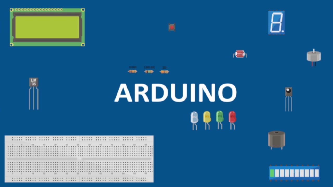
motor speed controller with arduino in tinkercad | motor speed controller with PWM in tinkercad
Summary
TLDRIn this tutorial, the presenter explains how to control the speed of a DC motor using an Arduino Uno and PWM (Pulse Width Modulation). They demonstrate the setup process with key components like the Arduino board, an NPN transistor, a DC motor, and a 220-ohm resistor. The tutorial walks through the wiring, code, and PWM signal adjustments to regulate the motor's speed, from zero RPM up to the motor’s maximum. The presenter provides clear step-by-step instructions and troubleshooting tips, making it easy for viewers to follow along and replicate the project.
Takeaways
- 😀 The tutorial demonstrates how to control the speed of a DC motor using an Arduino Uno and PWM (Pulse Width Modulation) technique.
- 😀 PWM works by generating pulses of varying duty cycles to adjust the motor speed.
- 😀 The Arduino Uno has specific PWM pins (3, 5, 6, 9, 10, 11) that can be used to control the motor speed.
- 😀 To interface the motor with the Arduino, an NPN transistor is used to handle the motor's power requirements.
- 😀 A 220-ohm resistor is needed to limit the current going to the transistor's base and avoid damage from excessive voltage.
- 😀 The circuit is powered by four batteries, and the motor is connected to the transistor's emitter and the battery's ground.
- 😀 The code example initializes a PWM pin and starts by setting the motor speed to 0 (no rotation).
- 😀 The speed of the motor increases by changing the PWM value, with the motor's RPM rising as the duty cycle is increased.
- 😀 After troubleshooting connections, including grounding the Arduino, the motor begins to rotate at speeds up to 8,000 RPM when the PWM value is set to 255.
- 😀 The motor's speed can be adjusted by varying the PWM value from 0 (no rotation) to 255 (maximum speed).
- 😀 The tutorial concludes by showing how to control the speed of the motor effectively using the PWM technique in Arduino programming.
Q & A
What is the purpose of using Pulse Width Modulation (PWM) in this tutorial?
-PWM is used to control the speed of the DC motor by varying the duty cycle of the signal sent to the motor, which in turn adjusts its speed.
Which pins on the Arduino Uno are used for PWM?
-The PWM-capable pins on the Arduino Uno are pins 3, 5, 6, 9, 10, and 11.
Why is an NPN transistor used in this project?
-An NPN transistor is used to switch the higher current needed to drive the motor, as the Arduino alone cannot provide sufficient current for the motor.
Why is a 220-ohm resistor used in the circuit?
-The 220-ohm resistor is used to limit the current going into the base of the NPN transistor to prevent damage and ensure proper transistor operation.
What role does the 5V signal from the Arduino play in the circuit?
-The 5V signal from the Arduino is applied to the base of the NPN transistor through the 220-ohm resistor, allowing it to control the current flow through the motor.
What happens when the duty cycle is set to 0 in the code?
-When the duty cycle is set to 0, the motor does not rotate because the PWM signal's positive portion is zero, meaning no power is delivered to the motor.
What should you do if the motor is not running initially in the simulation?
-Check the ground connections. The Arduino ground, motor ground, and battery ground must all be connected for the circuit to work correctly.
How does increasing the PWM value affect the motor's speed?
-Increasing the PWM value increases the duty cycle of the signal, delivering more power to the motor and causing it to spin faster.
What is the maximum motor speed achievable in this setup?
-The maximum motor speed achievable in this setup is around 8,000 RPM, which occurs when the PWM value is set to 255.
How does the resistor value affect the motor's operation?
-The 220-ohm resistor limits the current flowing into the base of the transistor. If a lower resistor value were used, it could provide too much current, potentially damaging the components.
Outlines

This section is available to paid users only. Please upgrade to access this part.
Upgrade NowMindmap

This section is available to paid users only. Please upgrade to access this part.
Upgrade NowKeywords

This section is available to paid users only. Please upgrade to access this part.
Upgrade NowHighlights

This section is available to paid users only. Please upgrade to access this part.
Upgrade NowTranscripts

This section is available to paid users only. Please upgrade to access this part.
Upgrade NowBrowse More Related Video
Arduino - Aula 23 - Experimento 9 - Motor com potenciômetro
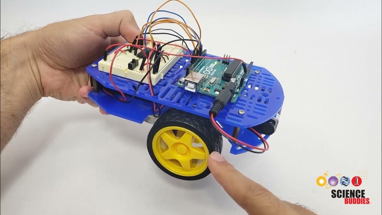
Arduino Self-Driving Car Lesson 3: Controlling Motor Speed

What is Pulse Width Modulation? How to generate PWM signal ? Pulse Width Modulation Explained
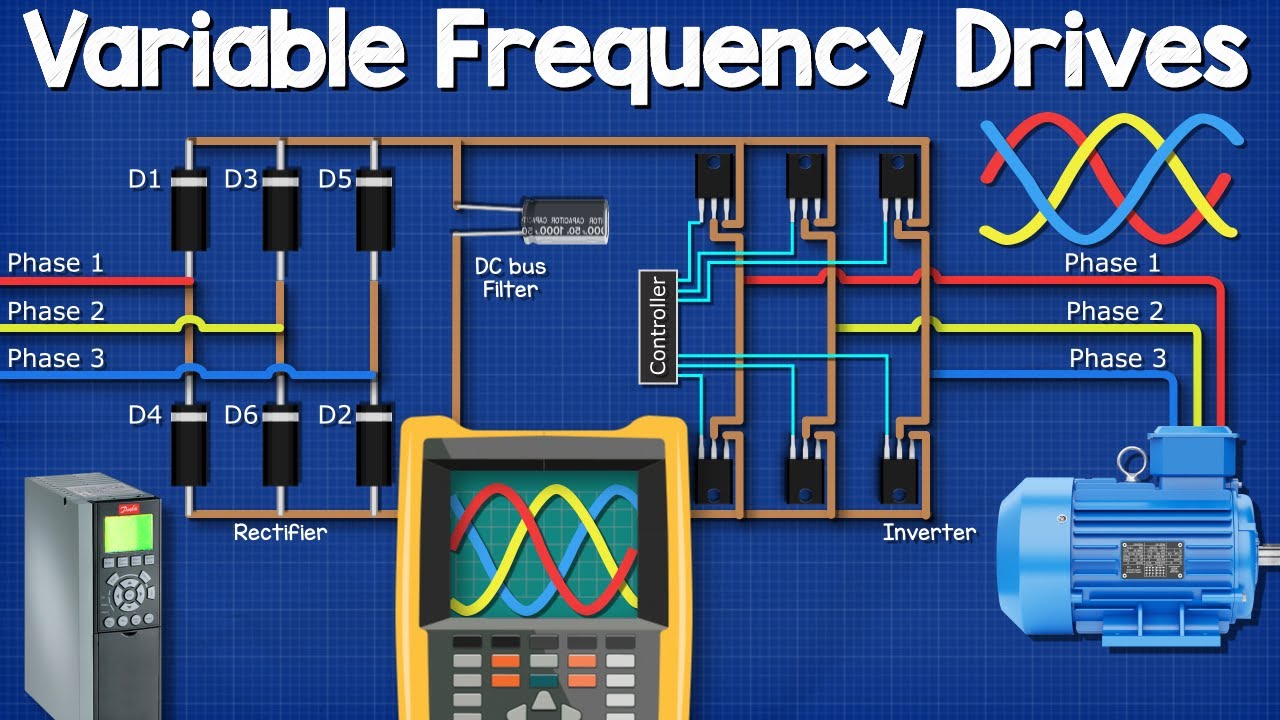
Variable Frequency Drives Explained - VFD Basics IGBT inverter

ESP32 Servo Motor Web Server with Arduino IDE

Inversor de Frequências _ Aula 1_ Conceitos Básicos
5.0 / 5 (0 votes)