Simple Diode Circuit Calculations 1. Ideal Diode

Dr Naser Sedghi
21 Aug 202011:22

Summary

TLDRThis educational video demonstrates a straightforward method for calculating current in a basic diode circuit using an ideal diode model, suitable for quick estimates without precise measurements. It explains the ideal diode's one-way current conduction and contrasts it with real diode characteristics. The video guides viewers through determining the diode's bias state and calculating current by substituting the diode with a short circuit in forward bias. It also addresses scenarios where the ideal diode model's accuracy varies with different applied voltages and covers the case when the diode is in reverse bias, emphasizing the importance of standard diode voltage and current notations.

Takeaways

  • 🔬 The video demonstrates a method to calculate current in a simple diode circuit using an ideal diode model, suitable for rough estimates.
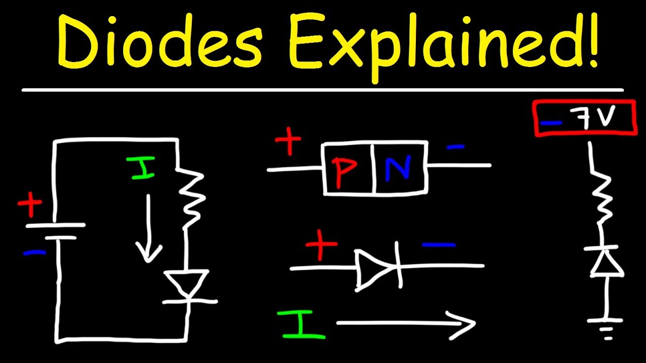
  • 🌟 An ideal diode allows current flow only in one direction, acting as an open circuit in reverse bias and a short circuit in forward bias.
  • 🔋 The video explains that in forward bias, the voltage across an ideal diode is zero, simplifying calculations.
  • 🔍 The script shows how to determine if a diode is in forward or reverse bias by examining the circuit's connections.
  • 📐 The calculation method involves replacing the diode with its equivalent circuit model and applying Kirchhoff's Voltage Law (KVL).
  • 🧮 The video provides a practical example where a 5-volt battery with a 2-kiloohm resistor results in a 2.5 milliamp current.
  • 📉 The ideal diode model is less accurate with small applied voltages, as it does not account for the real diode's forward voltage drop.
  • 🔌 When the diode is in reverse bias, the current is zero, and the entire voltage appears across the diode.
  • 📚 The video highlights the importance of standard notation for diode voltage and current, which can be negative in reverse bias.
  • 💡 The ideal diode model is a useful tool for quick calculations when the applied voltage is significantly higher than the forward voltage of a real diode.

Q & A

  • What is an ideal diode?

    -An ideal diode is a component that conducts current only in one direction. It behaves like a short circuit when forward biased and like an open circuit when reverse biased.

  • How does an ideal diode behave in forward bias?

    -In forward bias, an ideal diode conducts current and behaves like a short circuit, with zero voltage across it.

  • What happens when an ideal diode is in reverse bias?

    -In reverse bias, an ideal diode does not conduct current, behaving like an open circuit with zero current flowing through it.

  • How is current calculated in a simple diode circuit using an ideal diode model?

    -To calculate the current in the circuit, we replace the ideal diode with its short-circuit model (in forward bias), and apply Kirchhoff’s Voltage Law (KVL) to find that the current is equal to the applied voltage divided by the resistance (I = V/R).

  • Why might we use the ideal diode model for rough calculations?

    -The ideal diode model is used for rough calculations when precision is not critical, as it simplifies the circuit analysis, especially when the applied voltage is much larger than the forward voltage drop of a real diode.

  • What is the key difference between a real diode and an ideal diode?

    -The key difference is that a real diode has a forward voltage drop (typically 0.6 to 0.7 volts), whereas an ideal diode has no voltage drop when forward biased (zero volts).

  • When should the ideal diode model not be used?

    -The ideal diode model should not be used when the applied voltage is very small, as it introduces significant errors in calculating the current, especially when the forward voltage drop of a real diode becomes comparable to the applied voltage.

  • What is the voltage across the diode when it is in reverse bias?

    -When in reverse bias, the voltage across the diode is equal to the negative of the applied voltage, as there is no current flowing through the resistor.

  • How accurate is the ideal diode model for large applied voltages?

    -The ideal diode model is quite accurate for large applied voltages. For example, with 100V applied, the error is less than 1%, providing a reasonable approximation.

  • How can we determine if a diode is in forward or reverse bias in a circuit?

    -A diode is in forward bias when the anode is connected to a higher voltage than the cathode. If the cathode is at a higher voltage than the anode, the diode is in reverse bias.

Outlines

00:00

🔌 Understanding the Ideal Diode Model

This paragraph introduces the concept of an ideal diode and its use in calculating current in a simple diode circuit. The ideal diode is a theoretical model that allows current to flow in only one direction, acting as an open circuit when reverse-biased and a short circuit when forward-biased. The video explains that this model is suitable for rough estimates where precision is not critical. The characteristics of an ideal diode are contrasted with those of a real diode, highlighting the negligible reverse saturation current and the zero voltage drop in forward bias. The video then demonstrates how to determine if the diode in the circuit is in forward or reverse bias, using the connection of the battery to the diode as a guide. The diode is identified as being in forward bias due to the direction of the current from anode to cathode. The calculation of the current through the diode is simplified by treating the diode as a short circuit in forward bias, leading to the formula I_D = V/R, where I_D is the diode current, V is the voltage, and R is the resistance. The example provided calculates a current of 2.5 milliamps for a 5-volt battery and a 2-kiloohm resistor.

05:03

🔋 Ideal Diode Model in Forward and Reverse Bias

This paragraph delves into the accuracy of the ideal diode model in different scenarios. It explains that the model can be quite accurate when the applied voltage is significantly higher than the forward voltage of a real diode, which is typically around 0.6 to 0.7 volts. The video provides examples of current calculations with different voltages, showing that the ideal diode model's accuracy decreases as the applied voltage gets closer to the forward voltage of a real diode. The paragraph also addresses the case when the diode is in reverse bias, stating that by definition, the current through an ideal diode in reverse bias is zero. The video then discusses the standard notation for diode voltage and current, emphasizing that these values are negative when the diode is in reverse bias. The equivalent circuit for a reverse-biased diode is described as an open circuit, confirming the zero current flow. The video concludes with a KVL (Kirchhoff's Voltage Law) equation for the reverse-biased scenario, which confirms that the voltage across the diode equals the negative of the applied voltage.

10:03

📉 Analyzing Diode Voltage in Reverse Bias

The final paragraph focuses on the voltage across the diode when it is in reverse bias. It begins by setting up a KVL equation for the circuit, considering the diode as an open circuit with zero current flow. The equation simplifies to V_D = -V, where V_D is the voltage across the diode and V is the applied voltage. The video confirms that with no current in the circuit and no voltage drop across the resistor, the entire applied voltage appears across the diode. This reinforces the concept that in reverse bias, the ideal diode acts as an open circuit, and all the applied voltage is reflected across it. The video ends with a thank you note to the viewers.

Mindmap

Keywords

💡Diode

A diode is an electronic component that allows current to flow in one direction only, acting as a one-way valve. In the video, the diode is central to the explanation of how circuits work, specifically how it behaves in forward and reverse bias. The ideal diode conducts current only in the forward direction and blocks it in the reverse direction.

💡Ideal Diode

An ideal diode is a theoretical model of a diode that conducts current perfectly in one direction with zero resistance and blocks all current in the opposite direction with infinite resistance. In the video, the ideal diode model is used for simplifying calculations, especially when precise current values are not necessary.

💡Forward Bias

Forward bias refers to the condition where the positive terminal of the battery is connected to the anode of the diode, allowing current to flow through the diode. In the video, this concept is important because it explains how the diode allows current to pass and how the voltage across it becomes zero in this state.

💡Reverse Bias

Reverse bias occurs when the positive terminal is connected to the cathode of the diode, preventing current from flowing through the diode. The video explains that in reverse bias, the diode can be modeled as an open circuit with zero current flow, illustrating how the ideal diode behaves in this scenario.

💡Current (I)

Current is the flow of electric charge in a circuit, measured in amperes. The video explains how to calculate the current in a diode circuit using the relationship I = V/R, where voltage is divided by resistance. In forward bias, the current flows through the diode, while in reverse bias, it is zero.

💡Voltage (V)

Voltage is the electric potential difference between two points in a circuit, measured in volts. The video shows how voltage behaves across a diode in different conditions, such as being zero when the diode is in forward bias and equal to the applied voltage when in reverse bias.

💡Resistance (R)

Resistance is the opposition to the flow of current in a circuit, measured in ohms. The video uses resistance in the calculation of current, where R plays a key role in determining the amount of current flowing through the circuit based on the applied voltage.

💡Kirchhoff's Voltage Law (KVL)

Kirchhoff's Voltage Law states that the sum of all voltages around a closed loop in a circuit must equal zero. The video applies this law to explain how the voltage across different components in the diode circuit can be calculated, helping to understand the overall voltage distribution.

💡Short Circuit

A short circuit is a low-resistance connection between two points in a circuit that allows a large amount of current to flow. In the video, the ideal diode in forward bias is modeled as a short circuit because the voltage across it is zero, which means it acts like a closed switch.

💡Open Circuit

An open circuit occurs when there is a break in the circuit, preventing current from flowing. The video explains that in reverse bias, the diode behaves as an open circuit, meaning no current passes through it, similar to an open switch.

Highlights

Introduction to calculating current in a simple diode circuit using the ideal diode model.

Explanation that the method is suitable for rough estimates and not for precise values.

Definition of an ideal diode and its one-way current conduction property.

Modeling an ideal diode as an open circuit in reverse bias and a short circuit in forward bias.

Comparison of ideal diode characteristics with those of a real diode, highlighting differences in forward bias voltage.

Procedure to determine if the diode is in forward or reverse bias by examining the battery connections.

Calculation of current in the circuit by replacing the diode with a short circuit model.

Application of Kirchhoff's Voltage Law (KVL) to find the current in the loop.

Mental calculation shortcut for current without KVL by using Ohm's Law.

Explanation of how to calculate the voltage across the diode when it's in forward bias.

Discussion on the accuracy of the ideal diode model for different applied voltages.

Example calculation showing a small error in current estimation with high applied voltage.

Example calculation demonstrating a significant error in current estimation with low applied voltage.

Advice against using the ideal diode model for circuits with very small applied voltages.

Procedure for calculating current when the diode is in reverse bias, resulting in zero current.

Explanation of diode voltage notation and its significance in reverse bias.

Final thoughts on the practicality of the ideal diode model for different circuit analysis scenarios.

Transcripts

play00:03

hi everyone

play00:04

in this video i will show how to

play00:06

calculate the current

play00:07

in a simple dial circuit using the ideal

play00:10

diode

play00:12

this is the simplest method and even can

play00:14

be done without using pen and paper

play00:17

it is used when we want to have a rough

play00:20

estimate of the current

play00:21

and the precise value is not needed

play00:30

this is a simple diode circuit in fact

play00:33

most diode circuits

play00:34

can be simplified to this circuit let's

play00:37

first see

play00:38

what is the deflation of an ideal diode

play00:41

and how

play00:42

is its characteristics an ideal diode

play00:45

can conduct current only in one

play00:47

direction

play00:48

and no current can go to the opposite

play00:50

direction

play00:56

if the voltage across the diode is

play00:58

negative

play00:59

no current goes through the diode or the

play01:02

current

play01:02

is zero it is said the diode is in

play01:05

reverse bias

play01:10

it can be modeled as an open circuit

play01:13

or an open switch

play01:20

when the current goes through the diode

play01:23

the voltage across it is zero this is

play01:26

like a short circuit or closed switch

play01:30

and it is said the diode is in forward

play01:32

bias

play01:33

for comparison the characteristics of a

play01:36

real diode are shown here

play01:38

in reverse bias

play01:42

the ideal diode has a very good match

play01:45

with the real diode

play01:46

because it has the reverse saturation

play01:49

current

play01:50

which is negligible and usually is

play01:52

assumed

play01:53

zero at forward waves you can see

play01:56

more difference the real diode has a

play01:59

voltage of about

play02:00

0.6 or 0.7 volts but the voltage of the

play02:04

ideal diode is defined

play02:06

as zero i will talk about this

play02:08

difference

play02:09

later in this video now let's calculate

play02:13

the current in this circuit

play02:15

first we need to find out if the diode

play02:18

is in forward waves or in reverse bias

play02:22

the positive side of the battery is

play02:24

connected to the anode of the diode

play02:28

and the cathode is connected to the

play02:30

negative side of the battery

play02:32

through the resistor r therefore the

play02:36

current

play02:36

goes from the positive side to the

play02:39

negative side

play02:40

and it is in direction of anode to

play02:43

cathode

play02:44

and the diode is in forward bias

play02:50

the arrow shape of the diode shows the

play02:52

direction that the diode conducts the

play03:02

current

play03:04

to calculate the current we simply

play03:07

replace the diode

play03:09

with its model or equivalent circuit

play03:12

in forward bias which is a short circuit

play03:18

then we can write a kvl in this loop

play03:22

we have v equals to

play03:25

r times i

play03:29

and equal to r times id

play03:33

the current in the loop is the current

play03:36

in the diode

play03:39

from here we can calculate id

play03:43

equal to v divided by r

play03:47

and if we put the numerical values

play03:51

5 volts divided by 2 kilo

play03:54

equals to 2.5

play04:00

milliamps

play04:08

remember that if you use the value of

play04:10

resistor with unit of kilo

play04:12

the current is found in milliamps

play04:19

here i have drawn the equivalent circuit

play04:21

and

play04:22

was writing a kvl equation only for

play04:26

explanation and for clarification

play04:29

we really don't need to do that by

play04:32

looking

play04:33

at the circuit

play04:37

we can even have a mental calculations

play04:40

5 volts divided by 2 kilo ohms is

play04:44

2.5 milliamps what about the voltage

play04:48

across the diode

play04:50

it is a short circuit and short circuit

play04:53

by definition

play04:54

doesn't hold any voltage or as the ideal

play04:57

diode is defined

play04:59

when it is in forward west its voltage

play05:02

is zero so we can write

play05:06

vd or the voltage across the diode

play05:10

equals to zero volts

play05:18

when we use the ideal diode model

play05:22

it is when we want to have a rough

play05:25

calculation

play05:26

and the precise value of the current is

play05:28

not very important

play05:35

the method can be quite accurate if the

play05:38

if the applied voltage is very large

play05:42

much larger than the forward voltage of

play05:44

the real diode

play05:45

which is usually 0.6 2.7 volts

play05:50

for example if the voltage is 100 volts

play05:55

the current is calculated as

play06:02

50 milliamps

play06:11

the precise value is around 49.7

play06:18

milliamps

play06:20

and the difference is about 0.6 percent

play06:24

or less than 1 percent

play06:28

for a voltage of 10 volts

play06:32

the calculated current is

play06:40

5 milliamps

play06:44

and the precise value

play06:49

the precise value is 4.7 milliamps

play06:53

about 6 percent different still good

play07:00

but what about if the applied voltage

play07:04

is 1 volt

play07:10

using the ideal diode we calculate

play07:13

the current equal to 0.5 milliamp

play07:21

the precise value is 0.2 milliamp

play07:27

a massive error more than two times

play07:31

so we should not use the ideal diode

play07:33

model

play07:34

when the applied voltage is very small

play07:46

what about the current when the diode is

play07:49

in reverse bias

play07:50

in this figure i have changed the

play07:52

direction of the diode

play07:54

so the cathode voltage is more positive

play07:58

than a node voltage

play08:03

instead of changing the

play08:06

diode direction we can change the

play08:09

polarity of the battery

play08:11

negative on top and positive at the

play08:14

bottom

play08:15

it would be the same

play08:26

calculate the current actually we don't

play08:29

need to

play08:30

do anything to calculate the current

play08:33

because by definition

play08:34

the ideal diode in reverse bias has a

play08:37

current of zero

play08:39

so the current is zero

play08:44

but if you want you can draw the

play08:47

equivalent circuit of the diode

play08:50

in reverse

play08:56

which is an open circuit and hence

play08:59

the current is zero

play09:16

it is important that the standard

play09:20

notation of the diode voltage is

play09:23

the voltage of a node in respect of the

play09:25

cathode

play09:27

and the standard notation of the diode

play09:29

current

play09:30

is from anode to cathode

play09:34

if the diode is in reverse bias

play09:37

these values will be negative

play09:43

so here i actually is

play09:47

equal to minus id but because it's zero

play09:50

it doesn't matter

play09:59

what about the voltage across the diode

play10:02

we can write

play10:03

a kvl equation in the loop

play10:07

if we start from the left

play10:10

v equals to minus vd

play10:14

plus r times i

play10:18

and we know that the current is zero

play10:22

so this is equal to minus vd

play10:27

plus r times zero

play10:38

and from that we can find vd

play10:43

equal to minus v

play10:46

and equal to minus 5 volts

play10:53

this is very obvious because there is no

play10:57

current in the circuit

play10:59

there is no voltage drop across the

play11:01

resistor

play11:02

and all the applied voltage appears

play11:05

across the

play11:05

diode thanks for watching

play11:22

you

Rate This

5.0 / 5 (0 votes)

الوسوم ذات الصلة
Diode CircuitCurrent CalculationIdeal DiodeElectrical EngineeringCircuit AnalysisForward BiasReverse BiasVoltage DropOhm's LawElectronics Tutorial
هل تحتاج إلى تلخيص باللغة الإنجليزية؟