Understanding Shear Force and Bending Moment Diagrams
Summary
TLDRThis educational video script offers a comprehensive guide to understanding shear force and bending moment diagrams, essential tools for mechanical and civil engineers analyzing beams under load. It explains the internal forces within a beam, including shear and normal forces, and how they manifest in different beam conditions like sagging or hogging. The script outlines the steps to determine these forces, including drawing free body diagrams, calculating reaction forces and moments, and constructing shear force and bending moment diagrams. It also covers sign conventions, the impact of various loads, and how to use equilibrium equations for statically determinate beams. The video concludes with practical examples and tips for predicting beam deformations based on bending moments.
Takeaways
- 📚 Shear force and bending moment diagrams are essential tools for engineers to analyze beams under various loads.
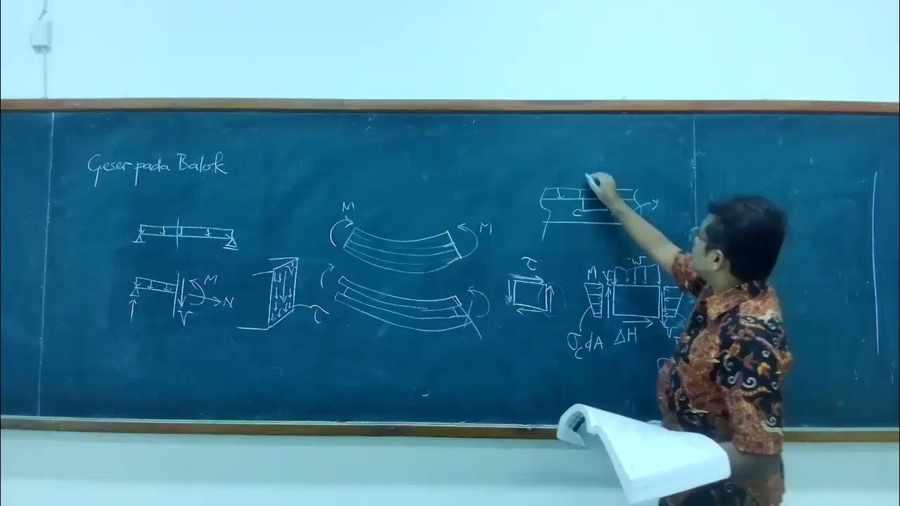
- 🔧 Internal forces in a beam consist of shear forces (vertical) and normal forces (along the beam's axis), which help maintain equilibrium.
- 📉 When a beam sags, the top experiences compression and the bottom experiences tension, leading to the development of bending moments.
- 📈 Shear forces and bending moments are represented as resultants on the beam's cross-section, simplifying the analysis of internal forces.
- 🏗️ Beams can be loaded with concentrated forces, distributed forces, or concentrated moments, and are supported in different ways like pinned, roller, or fixed supports.
- ⚖️ Reaction forces and moments at supports are determined using equilibrium concepts, leading to statically determinate or indeterminate beam analyses.
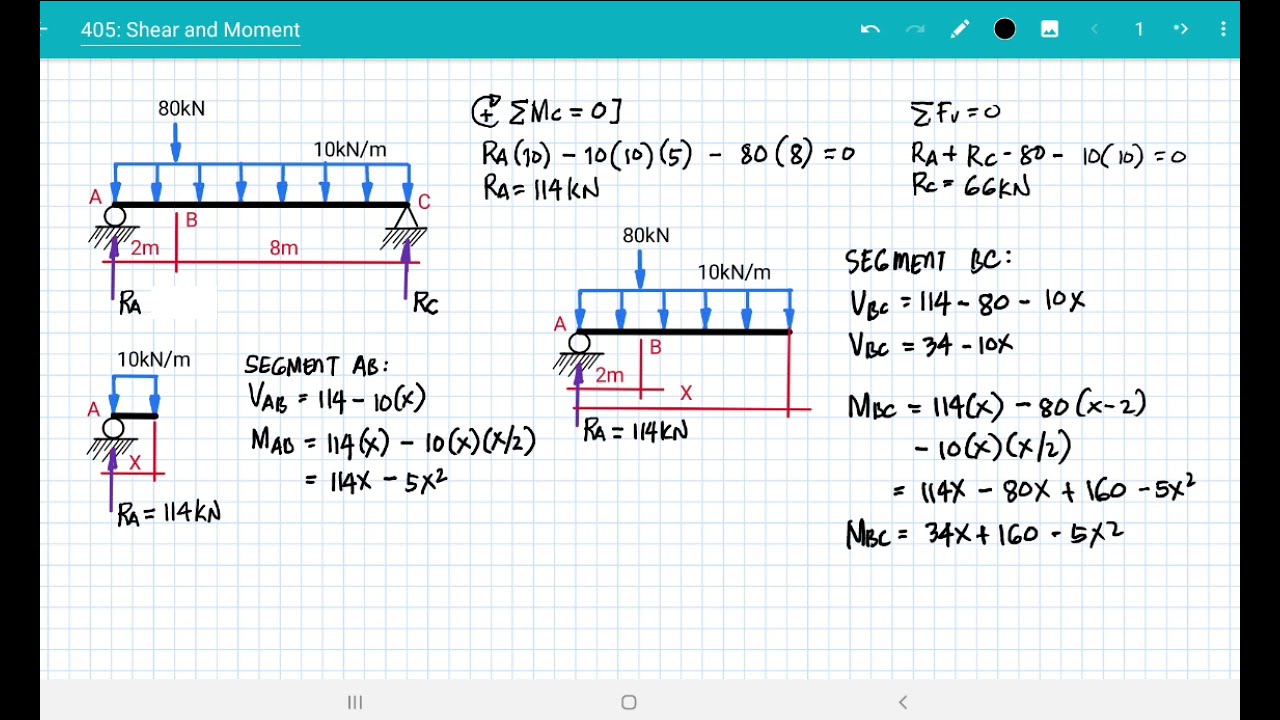
- 📉 The process of drawing shear force and bending moment diagrams involves calculating reaction loads and then determining internal forces at each beam location.
- 📌 Positive bending moments cause the lower section of the beam to be in tension, typically associated with sagging, while negative moments cause hogging.
- 🔍 Relationships between applied loads, shear forces, and bending moments can be used to construct or verify diagrams, such as the slope of the shear force curve being equal to the negative of the distributed load.
- 📊 The area under the shear force curve represents the change in bending moment, which is a useful method for diagram verification.
Q & A
What are shear force and bending moment diagrams?
-Shear force and bending moment diagrams are graphical methods used by engineers to analyze the internal forces within a beam under various loads. They help visualize how a beam responds to different types of loading.
Why are shear forces and bending moments important in beam analysis?
-Shear forces and bending moments are crucial for understanding the internal forces that develop within a beam when it is loaded. They are essential for determining the beam's structural integrity and predicting its behavior under load.
What are the two components of internal forces in a beam?
-The two components of internal forces in a beam are shear forces, which are oriented in the vertical direction, and normal forces, which are oriented along the axis of the beam.
How do you represent the internal forces acting on a beam cross-section?
-The internal forces acting on a beam cross-section are represented using two resultants: one shear force, which is a resultant of the vertical internal forces, and one bending moment, which is a resultant of the normal internal forces.
What are the different types of loads that can act on a beam?
-Beams can be loaded by concentrated forces, distributed forces, and concentrated moments. These loads affect the shear force and bending moment diagrams and thus the beam's behavior.
What are the common types of beam supports and how do they affect the beam?
-Common types of beam supports include pinned supports, roller supports, and fixed supports. Pinned supports allow rotation but prevent vertical and horizontal displacements, roller supports prevent vertical displacement but allow horizontal displacement and rotation, and fixed supports prevent all displacements and rotation.
What is a statically determinate beam and how is it different from a statically indeterminate beam?
-A statically determinate beam is one where all the reaction forces and moments can be calculated using equilibrium equations. In contrast, a statically indeterminate beam has more unknowns than can be solved with the available equilibrium equations, requiring more complex methods to solve.
How do you determine the shear forces and bending moments within a beam?
-To determine the shear forces and bending moments within a beam, you follow three main steps: draw a free body diagram of the beam, calculate the reaction forces and moments at the supports using equilibrium, and then calculate the internal shear forces and bending moments at each location along the beam.
What is the significance of the sign convention in shear force and bending moment diagrams?
-The sign convention in shear force and bending moment diagrams is important for consistency and clarity in analysis. Applied forces are positive if they act downwards, and positive shear forces and bending moments are defined based on their orientation and effect on the beam's cross-section.
How can the relationships between applied loads, shear forces, and bending moments help in constructing diagrams?
-The relationships between applied loads, shear forces, and bending moments can be used to derive equations for the shear force and bending moment curves. These relationships help in constructing accurate diagrams and performing sense checks by comparing calculated values with expected changes in the diagrams.
What insights can be gained from the shear force and bending moment diagrams about the deformed shape of a beam?
-The shear force and bending moment diagrams can be used to predict the deformed shape of a beam. Positive bending moments indicate sagging, negative bending moments indicate hogging, and zero bending moments suggest a straight section of the beam.
Outlines

هذا القسم متوفر فقط للمشتركين. يرجى الترقية للوصول إلى هذه الميزة.
قم بالترقية الآنMindmap

هذا القسم متوفر فقط للمشتركين. يرجى الترقية للوصول إلى هذه الميزة.
قم بالترقية الآنKeywords

هذا القسم متوفر فقط للمشتركين. يرجى الترقية للوصول إلى هذه الميزة.
قم بالترقية الآنHighlights

هذا القسم متوفر فقط للمشتركين. يرجى الترقية للوصول إلى هذه الميزة.
قم بالترقية الآنTranscripts

هذا القسم متوفر فقط للمشتركين. يرجى الترقية للوصول إلى هذه الميزة.
قم بالترقية الآن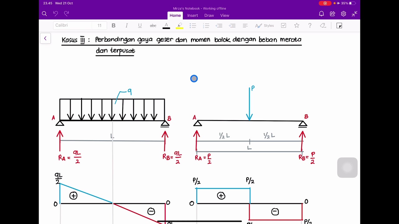


5.0 / 5 (0 votes)
