Part 1: Introduction to Testing Battery Management System (BMS) Software
Summary
TLDRIn this video, MathWorks' engineers Francesco Alderisio and Maurizio Dalbard introduce methods and techniques for verifying, validating, and testing Battery Management System (BMS) requirements using Simulink. They demonstrate the model-based design process, emphasizing the importance of early validation to catch errors efficiently. The session covers the system analysis, including the plant components and the BMS ECU, and highlights the role of Stateflow in implementing state machines for different operational modes. The presentation also touches on the Model-Based Design workflow's benefits, including its ability to meet stringent certification standards like ISO 26262 for automotive software development.
Takeaways
- 🔧 Francesco Alderisio and Maurizio Dalbard from MathWorks are presenting methods and techniques for verifying, validating, and testing BMS requirements using Simulink before software deployment.
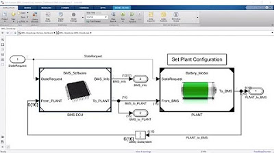
- 🛠️ The system analysis includes a controller, plant components like a battery pack, recharge circuit, and charger/load, with physical connections and electrical components highlighted.
- 🔌 The pre-charge circuit has six switching devices that need to be controlled to prevent electrical spikes.
- 🔋 The battery pack model includes six cells in series and thermal behavior via convection, along with a cell monitoring unit for charge balancing.
- 🤖 The BMS ECU model comprises different components for tasks like balancing logic, SOC estimation, and a state machine implemented in Stateflow.
- 🔄 The state machine includes parallel states for standby, charging, driving modes, fault monitoring, and contactor control to prevent spikes.
- 🔍 The Model-Based Design workflow is emphasized for early identification of errors, with a shift from ambiguous designs to graphical models for precise software specification.
- 📈 The cost of finding bugs increases over time, making early validation in the design process crucial for cost-effectiveness.
- 🛑 Simulation is an early validation tool, but a more rigorous approach is needed for systematic testing to ensure all requirements are met.
- 📚 The complete Model-Based Design process allows for earlier and more cost-effective error identification, with simulation and testing integrated into the workflow.
- 🏢 Companies like LG have used this workflow to develop BMS software for hybrid vehicles, achieving ISO 26262 SLC certification for AUTOSAR code.
- 📘 The Model-Based Design workflow is part of a development process approved by TUV certification authority, with documentation included in the IEC Certification Kit and DO Qualification Kit.
Q & A
What is the role of Francesco Alderisio in the presentation?
-Francesco Alderisio is an application engineer at MathWorks, and he is the presenter who introduces the topic of verifying, validating, and testing BMS (Battery Management System) requirements using Simulink.
Who is Maurizio Dalbard and what does he contribute to the presentation?
-Maurizio Dalbard is a Senior Application Engineer at MathWorks. He provides an overview of the Model-Based Design workflow, focusing on verification and validation, and discusses the importance of systematic testing in the development process.
What is the purpose of the system analysis presented in the script?
-The system analysis is aimed at understanding the components and connections within a BMS, including the controller, plant, battery pack, recharge circuit, charger, and load, to ensure proper control and avoid undesired electrical spikes.
What are the different components of the plant mentioned in the script?
-The plant consists of a battery pack, a recharge circuit, and a charger and load setup, each with specific components such as switching devices and thermal behavior models.
How many cells are connected in series in the battery pack model?
-In the battery pack model, there are six different cells connected in series.
What is the role of the cell monitoring unit in the BMS?
-The cell monitoring unit is responsible for controlling other switching devices to maintain a balanced state of charge across the different cells in the battery pack.
What are the four different model references mentioned in the BMS ECU?
-The four model references in the BMS ECU include a balancing logic, an SOC (State of Charge) estimation model, a state machine implemented in Stateflow, and fault monitoring states.
What is the significance of the state machine in the BMS ECU?
-The state machine in the BMS ECU is crucial as it implements logic to manage different states such as standby, charging, driving modes, and fault modes, ensuring the system operates correctly under various conditions.
What are the advantages of using Simulink for verifying and validating BMS requirements?
-Simulink allows for the use of graphical models or executable specifications that provide precise meanings, making it easier to identify errors early in the design phase, reducing the cost and complexity of bug detection.
How does the Model-Based Design process help in reducing the cost of finding bugs?
-The Model-Based Design process enables early validation of the design through simulation, which is more cost-effective than testing in the final phase, as errors are cheaper and easier to identify early on.
What is the significance of the IEC Certification Kit and DO Qualification Kit mentioned in the script?
-The IEC Certification Kit and DO Qualification Kit provide complete documentation for the Model-Based Design workflow, which is essential for developing critical embedded software that meets the standards required for certification by authorities such as TUV.
Outlines
🛠️ Introduction to BMS Verification and Testing in Simulink
Francesco Alderisio and Maurizio Dalbard, both from MathWorks, introduce a session focused on Battery Management System (BMS) requirements verification, validation, and testing using Simulink. They discuss the importance of adopting methods and techniques to ensure the software's readiness for deployment on embedded microprocessors. The session begins with an analysis of the system components, including a controller, plant, battery pack, recharge circuit, and charger with their respective connections and functions. The battery pack is further detailed with its series-connected cells and thermal behavior modeling. The BMS ECU is highlighted with its various model references, including balancing logic, SOC estimation, and a state machine implemented in Stateflow, which manages different states such as standby, charging, driving, and fault monitoring. The overview also touches on the control of contactors to prevent electrical spikes. The presenters encourage viewers to refer to another webinar for more details on the passive balancing logic.
🔍 Model-Based Design for BMS Software Verification and Validation
Maurizio Dalbard provides an in-depth look at the Model-Based Design workflow, emphasizing the verification and validation stages in the development of critical embedded software like a BMS. He explains the transition from requirements to design specifications and the challenges of identifying errors in traditional processes due to the lack of simulation capabilities. Dalbard highlights the benefits of using Simulink for creating graphical models or executable specifications that facilitate early and cost-effective error detection. The Model-Based Design process is positioned as a way to validate the design early in the development cycle, reducing the cost of bug fixes over time. The session outlines the need for a more rigorous approach to testing the model systematically to ensure all requirements are met and the system functions correctly. Dalbard also mentions the integration of verification, validation, and test activities into the workflow, including component and system testing, review, and static analysis. The presentation concludes with examples of companies like LG, which have successfully used the Model-Based Design workflow to achieve ISO 26262 SLC certification for AUTOSAR code in BMS development, with complete documentation provided in the IEC Certification Kit and DO Qualification Kit.
Mindmap
Keywords
💡Application Engineer
💡Simulink
💡BMS Requirements
💡Embedded Microprocessor
💡Plant
💡Switching Devices
💡State Machine
💡Fault Monitoring
💡Model-Based Design
💡Verification and Validation
💡IEC Certification Kit
Highlights
Francesco Alderisio and Maurizio Dalbard from MathWorks demonstrate methods and techniques in Simulink for verifying, validating, and testing BMS requirements before deploying software onto an embedded microprocessor.
The system being analyzed consists of a controller, plant with a battery pack, recharge circuit, charger, and load, highlighting the physical connections between electrical components.
Six switching devices in the pre-charge circuit need to be controlled to avoid undesired spikes between the battery, charger, and load.
The battery pack model includes six cells connected in series and thermal behavior modeled by convection.
The cell monitoring unit allows for control of switching devices to maintain a balanced state of charge across different cells.
The BMS ECU model references include balancing logic, SOC estimation, and a state machine implemented in Stateflow with different parallel states for various modes and fault monitoring.
The Model-Based Design workflow is presented with a focus on verification and validation, emphasizing the importance of catching errors early in the design phase.
Simulink replaces ambiguous designs with graphical models or executable specifications to provide precise meanings and facilitate code generation.
Model-Based Design allows for earlier validation of the design where errors are cheaper and easier to identify.
Simulation is a great way to validate behavior early, but a more rigorous approach is needed for systematic testing to ensure all requirements are met.
The complete Model-Based Design workflow enables developers to gain confidence in the correctness of their designs through verification, validation, and testing activities.
The Model-Based Design workflow for developing critical embedded software is reviewed and approved by the TUV certification authority, with complete documentation included in the IEC Certification Kit and DO Qualification Kit.
LG used the Model-Based Design workflow to develop BMS software for a hybrid vehicle, achieving ISO 26262 SLC certification for AUTOSAR code.
The webinar provides an overview of the model and references to more detailed information on passive balancing logic and other components of the BMS development process.
Maurizio Dalbard emphasizes the importance of a rigorous testing approach in the Model-Based Design process to ensure the correctness and functionality of the design.
The presented workflow and techniques are part of a development process that has been certified and documented according to industry standards, ensuring reliability and compliance.
Transcripts
Hello everyone, my name is Francesco Alderisio and I'm an application engineer at
MathWorks. Today I've been joined by my colleague Maurizio Dalbard, Senior
Application Engineer. Today we will show you the methods and techniques
that you can adopt in Simulink to verify validate and test BMS requirements
before deploying the software onto an embedded microprocessor. So let's start
by analyzing the system that we have here. So we have a controller, and then we
have a plant, so let's go into the plant. And here we can recognize three
different components: battery pack, a recharge circuit, and then charger and
load. And here you can see the physical connections between the electrical
components. So let's go into the pre-charge circuit and here you can see
that we have six different switching devices that we need to appropriately
control so that we can avoid undesired spikes between the battery and between
the charger and the load. Let's go back and now let's analyze the battery pack.
So here we have two more components in particular. Here we can see that we have
six different cells connected in series, and then we have also modeled the
thermal behavior by convection. Okay then here we have the cell monitoring unit. So
in particular, here we have other switching devices that we can
appropriately open and close with our controller, so as the balanced state of
charge of the different cells.
Okay so now let's go into the BMS ECU. So here we have four different model
references. So we have different components that do different tasks. In
particular we have a balancing logic to balance the set of charge of the cells.
We have an SOC estimation model to estimate the set of charge of our cells
and then we have here the main component which we will analyze today, which is the
state machine. And here we have implemented a logic in Stateflow. In
particular we have different states that run in parallel, so we have the main
state machine in which we can see that we have a standby mode charging mode a
driving mode and so on. And we also have a fault mode. Then we have a fault
monitoring state, where we can monitor folds on the current faults on a
temperature or folds on the cell voltages. And then we have two more
parallel states where we can actually control the contactors in our model so
that we can avoid spikes. We have one for the inverter and then one for the
charger. Okay so this was a very brief overview of the model. If you want to
have more details on how this was built and more details on the passive
balancing logic please refer to the webinar battery management system
development Simulink where our colleague Javier will walk you through it.
Thank you Francesco for the introduction. Hi everyone, my name is Maurizio Dalbard. I'm in
application engineering at MathWorks. Before starting by seeing in practice
the methods and techniques you can adopt in Simulink to verify, validate, and test, I
would like to give you another view of the Model-Based Design workflow with a
more specific focus on verification and validation in the traditional process. We
start from the requirements that are refined into design specification. And
under is a gap in the process that we have to fill to the end written code.
Using this process, it is difficult to find the errors especially in the
initial design, because we can't simulate and we can just test in the final phase.
Many studies also show that the cost of finding a bug increases over time. In
the Model-Based Design process, Simulink replaces ambiguous designs using
graphical models or executable specifications that have precise
meanings, adding some some information about the software. And the targets will
obtain the model ready for cogeneration so that similar designs can be
automatically converted into code that we can download in our final target. With
the complete Model-Based Design process, you can validate your design here
earlier where errors are cheaper and easier to identify. Simulation
is a great way to validate behavior early but it is mainly among our forces
and largely ad hoc. And to define if all requirements are met and functioning
correctly we need to take a more rigorous approach to systematically test
our model in order to get the complete confidence in the correctness
of our designer using a complete Model-Based Design workflow.
So now adding some verification validation and test activities we have
to do some component and system testing, review and static analysis equivalent
testing, and we run and checked in, for example the motor position workflow is
complete. Step by step we'll touch some of the many techniques we can leverage
in Simulink to get more confidence in the correctness of our designs. This workflow is
a workflow to develop critical embedded software that was
reviewed and approved by the TUV certification authority. And there is
complete documentation describing it included in the IEC Certification Kit
and DO Qualification Kit according to the standards. In this slide you can see
LG, using the Model-Based Design workflow, developed software for a BMS
for a hybrid vehicle achieving the ISO 26262 SLC certification
for AUTOSAR code.
5.0 / 5 (0 votes)