52/2025 - AE1 - Mecânica e Resistência dos Materiais
Summary
TLDRThis video tutorial explains the process of evaluating the structural integrity of a metallic framework. The focus is on calculating normal stress in bars AB and BC, determining shear stress in a pin connection at point A, and assessing whether the material can withstand the applied stress. The video provides details on dimensions, applied loads, and material properties for precise calculations. Viewers are guided through essential steps in analyzing the structure to ensure safety and compliance with strength standards, particularly comparing the calculated stress values with the allowable material strength.
Takeaways
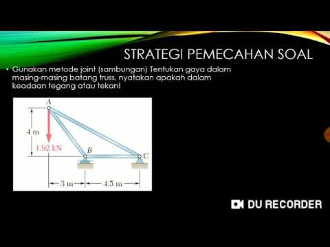
- 😀 The task involves analyzing a metallic structure subjected to a load of 30 kN at point B.
- 😀 The structure has three key points: A, B, and C, with points A and C fixed to a surface.
- 😀 The distance between points A and C is 1.5 meters, and between A and B is 2 meters.
- 😀 Several important dimensions, such as 50 mm and 40 mm, are provided for the structure.
- 😀 The diameter of a key part of the structure is 20 mm.
- 😀 Different views of the structure are shown, including top views of bars AB and BC.
- 😀 The main task is to calculate the normal tension in bars AB and BC under the applied load.
- 😀 Additionally, the shear stress in the pin at point A, which fixes the structure, must be calculated.
- 😀 The material of the bars has a permissible tension of 200 MPa, and students must verify if the material can handle the applied tension.
- 😀 Students are expected to compare the calculated tensions with the permissible tension to determine if the material will support the applied load.
- 😀 The video emphasizes careful attention to the provided dimensions and the specific details of the structure to perform accurate calculations.
Q & A
What is the main objective of the activity described in the video?
-The main objective is to evaluate a specific point of a metal structure design to ensure it can support the applied load. The task involves calculating the normal stress in bars AB and BC, the shear stress on a pin at point A, and assessing whether the material can withstand the applied normal stress.
What is the applied load in the structure, and where is it located?
-The applied load is 30 kN, and it is applied downward at point B of the structure.
What are the key dimensions of the structure given in the script?
-The script provides several dimensions: the distance between points A and C is 1.5 meters, the distance between points A and B is 2 meters, the diameter of the bar at certain points is 20 mm, and other parts of the structure have specific dimensions of 50 mm and 40 mm.
What does the video ask the viewer to calculate in part A of the problem?
-In part A, the viewer is asked to calculate the normal stress in the bars AB and BC.
What is the significance of point A in the structure?
-Point A is where the structure is fixed to a surface and is also the location of a pin that connects the bars. The video asks to calculate the shear stress on this pin.
What does part B of the problem require the viewer to calculate?
-Part B asks the viewer to calculate the shear stress on the pin located at the connection point A.
What is the permissible stress for the material used in the structure, and how does it relate to the calculations?
-The material used in the structure has a permissible stress of 200 MPa. The calculations of the normal stress in the bars AB and BC need to be compared with this permissible value to determine if the material can withstand the applied stress.
How does the viewer determine if the material will support the applied tension?
-The viewer must compare the calculated normal stress in the bars AB and BC with the material's permissible stress of 200 MPa. If the calculated stress is lower than this value, the material will support the load; if it is higher, the material may fail.
What additional views of the structure are provided in the video, and how are they helpful?
-The video provides various views of the structure, including a front view, top view of the BC bar, and an auxiliary view of the AB bar. These views help identify the dimensions and configurations necessary for accurate calculations.
What is the role of the pin at point A in the structure's design?
-The pin at point A serves to fix the structure in place, connecting the bars. It is crucial in determining the shear stress in the structure, which is part of the problem the viewer needs to solve.
Outlines

此内容仅限付费用户访问。 请升级后访问。
立即升级Mindmap

此内容仅限付费用户访问。 请升级后访问。
立即升级Keywords

此内容仅限付费用户访问。 请升级后访问。
立即升级Highlights

此内容仅限付费用户访问。 请升级后访问。
立即升级Transcripts

此内容仅限付费用户访问。 请升级后访问。
立即升级浏览更多相关视频

SK04A Struktur Kayu Contoh soal Truss Part 1

NSCP 2015 LOAD PROVISION AND LOAD COMBINATIONS

Applications of Elasticity Concept of CBSE Class 11 - Extramarks
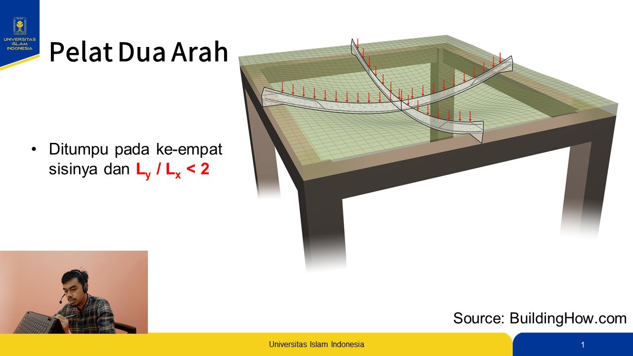
Desain Pelat 2 Arah Beton Bertulang - Part 2 - Pehitungan dengan Metode Koefisien Momen
Pembahasan Soal Analisis Struktur Truss dengan metode joint/sambungan

MACAM GAYA DALAM STRUKTUR BANGUNAN
5.0 / 5 (0 votes)
