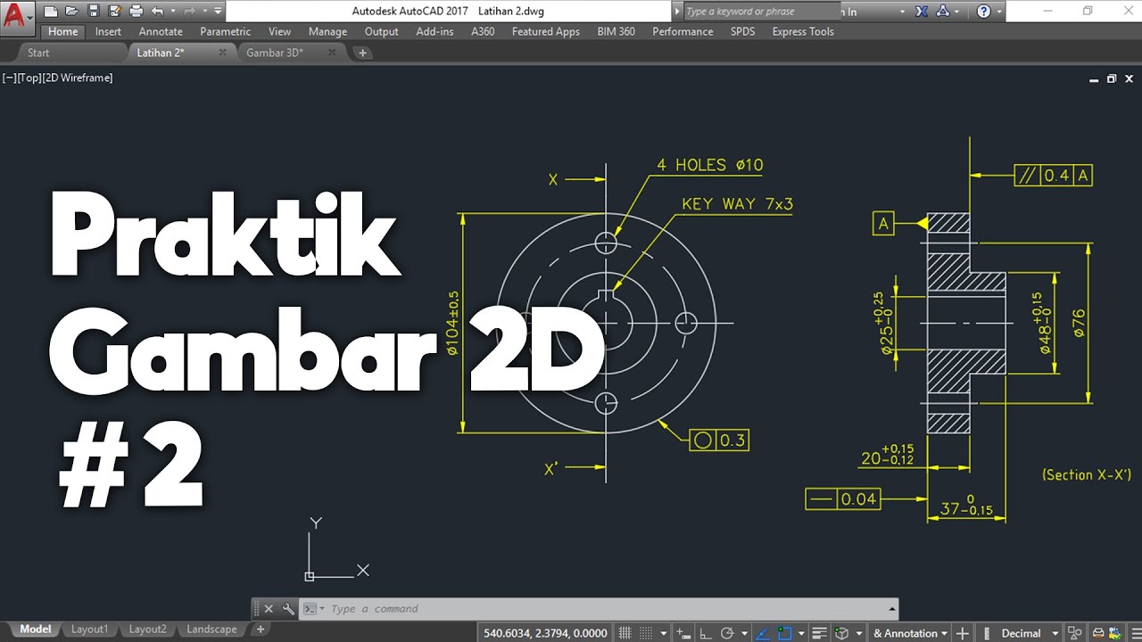
Fungsi dan Arti Arsiran Pada Perintah Hatch
Summary
TLDRIn this video, the host explains the basics of using 'head' (arsiran) symbols in AutoCAD, focusing on material representations for technical drawings. From cast iron (ANSI 31) to magnesium and aluminum (ANSI 38), the video breaks down the purpose and usage of each symbol. While some symbols, like ANSI 35 and 36, remain unclear, viewers are encouraged to share insights. The video concludes with a reminder to stay healthy and active, while teasing more content to come.
Takeaways
- 😀 The speaker encourages viewers to stay healthy due to the ongoing pandemic and emphasizes the importance of good health.
- 😀 The tutorial explains the 'hatch' function in AutoCAD, which is used to fill enclosed areas with patterns representing different materials.
- 😀 Hatch patterns (referred to as 'head') are essential in AutoCAD for illustrating materials in technical drawings.
- 😀 The ANSI codes for different hatch patterns are introduced, such as ANSI 31 for cast iron, ANSI 32 for steel, and ANSI 33 for bronze, brass, and copper.
- 😀 The speaker demonstrates how to select and use different hatch patterns in AutoCAD by typing the 'reg' command to create a rectangle.
- 😀 The video focuses on explaining some of the most commonly used ANSI codes for materials, such as ANSI 31 (cast iron), ANSI 32 (steel), and ANSI 33 (bronze, brass, and copper).
- 😀 The speaker mentions the challenge of finding information about ANSI codes 35 and 36 and asks for help from the audience regarding these codes.
- 😀 ANSI 37 represents zinc and alloys, which are commonly used in roofing and other construction materials.
- 😀 ANSI 38 is for magnesium and aluminum, materials commonly used in the aerospace industry and for lightweight structures like windows and doors.
- 😀 The tutorial encourages viewers to screenshot the material information for future reference and promises more content in the next video.
- 😀 The video ends with the speaker encouraging viewers to exercise and maintain their health.
Q & A
What is the purpose of the HE command in AutoCAD?
-The HE command in AutoCAD is used to create a hatch on closed areas, which helps in representing the material of the object or area in the drawing.
How do you create a hatch in AutoCAD using the HE command?
-To create a hatch, first, draw a closed shape like a rectangle using the 'REG' command. Then, type 'HATCH' or click the hatch icon, and select the desired pattern from the list of available hatches.
What does ANSI 31 represent in AutoCAD hatching symbols?
-ANSI 31 represents cast iron, also known as gray iron, and is often used in mechanical parts such as engine components.
What material is represented by the ANSI 32 hatching symbol?
-ANSI 32 represents steel, a widely used material in construction and manufacturing, known for its strength and durability.
What is the significance of ANSI 33 in AutoCAD hatching?
-ANSI 33 represents materials like bronze, brass, and copper, which are commonly used in items like medals and electrical components.
What does ANSI 34 symbolize in AutoCAD?
-ANSI 34 represents rubber and plastic materials, typically used in seals, gaskets, and flexible parts in various industries.
Why is there confusion regarding ANSI 35 and ANSI 36 symbols?
-There is a lack of clear documentation or standard definitions for ANSI 35 and 36 in AutoCAD, which makes it difficult to determine the specific materials they represent.
What materials are represented by the ANSI 37 hatch pattern?
-ANSI 37 represents zinc and alloys, which are commonly used in roofing and various alloy components, such as bicycle frames.
What is the application of the ANSI 38 symbol in AutoCAD hatching?
-ANSI 38 is used for materials like magnesium and aluminum, which are lightweight metals often found in aerospace and automotive industries.
How can AutoCAD users decide which hatch pattern to use for a specific material?
-Users should select the appropriate hatch pattern based on the material they are representing in their drawing. The patterns are predefined by standards like ANSI and can be chosen based on the material's properties and use case.
Outlines

此内容仅限付费用户访问。 请升级后访问。
立即升级Mindmap

此内容仅限付费用户访问。 请升级后访问。
立即升级Keywords

此内容仅限付费用户访问。 请升级后访问。
立即升级Highlights

此内容仅限付费用户访问。 请升级后访问。
立即升级Transcripts

此内容仅限付费用户访问。 请升级后访问。
立即升级浏览更多相关视频
AutoCAD Basic Tutorial for Beginners - Part 1 of 3
Aturan Gambar Teknik Mesin (Gambar Kerja) - Gambar Teknik Manufaktur

Pengenalan Gambar Teknik | Gamtek 40
Cara Menjalankan Perintah AutoCAD & Sistem Koordinat AutoCAD | Belajar AutoCAD dari Nol #4
Setting up LINE WEIGHTS with hierarchy in AutoCAD
Membuat Gambar Flange 2D dengan Toleransi Geometrik di AutoCAD
5.0 / 5 (0 votes)
