Circuito regulador velocidad motor DC con amplificadores operacionales (Clase 66)
Summary
TLDRThis video explains how a motor speed regulator works using a potentiometer and an inverting amplifier. The presenter demonstrates how to set the desired motor speed, adjusting the potentiometer to change voltage levels, which are then amplified and sent to the motor. The circuit continuously compares the desired speed with the actual speed, adjusting the motor's voltage to maintain the set speed. The system self-regulates, increasing or decreasing the motor's speed as needed, ensuring consistent operation. The video delves into the workings of feedback loops, error amplification, and motor control through voltage modulation.
Takeaways
- 🔧 The circuit presented is a motor speed regulator that uses operational amplifiers and feedback to control the speed of a DC motor.
- ⚡ The first stage of the circuit is a voltage follower controlled by a potentiometer, which allows the user to set a reference voltage (set-point) representing the desired motor speed.
- 🎚️ By adjusting the potentiometer, the reference voltage can vary approximately between +5 V and −5 V, determining the target speed for the motor.
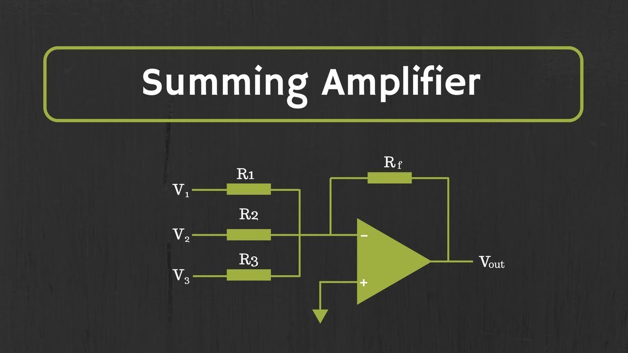
- 📊 The system compares the desired speed (set-point) with the actual motor speed using a summing inverting amplifier acting as a comparator.
- 🔁 The difference between desired speed and actual speed is called the error signal, which drives the control process.
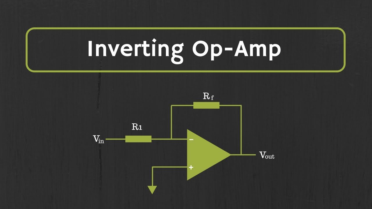
- 📈 This error signal is amplified by an inverting power amplifier with higher gain to generate sufficient voltage and current to drive the motor.
- ⚙️ The motor speed is controlled by the voltage applied to it: higher voltage increases speed, while lower voltage decreases speed.
- 🔄 A tachometric dynamo (tachogenerator) connected to the motor produces a voltage proportional to the motor’s real rotational speed.
- 🔌 The tachogenerator voltage is fed back into the circuit, creating a closed-loop feedback system that continuously corrects the motor speed.
- 🛡️ Protection diodes limit the output voltage to prevent the operational amplifier from exceeding the ±15 V supply rails.
- 🧲 Because the motor behaves as an inductive load, an RC network is added to make the load behave more like a resistive one and stabilize the circuit.
- 📉 The system uses a proportional controller, meaning a small steady-state error must exist for the system to maintain operation.
- 🔍 Through numerical examples, the script shows how changes in the reference voltage affect motor voltage, speed, and feedback values.
- 🔧 If the motor load increases (for example, adding a fan), the speed drops, which increases the error signal and automatically raises the motor voltage to restore the speed.
- 🤖 The circuit demonstrates automatic regulation: it keeps the motor speed close to the desired value despite disturbances or load changes.
Q & A
What is the primary function of the potentiometer in this circuit?
-The potentiometer in this circuit regulates the voltage applied to the motor, controlling its speed. By adjusting the potentiometer, the user can set the desired speed for the motor, with the voltage varying between +5V and -5V.
How does the circuit compare the desired motor speed with the real motor speed?
-The circuit compares the desired speed, set via the potentiometer, with the real motor speed by using a tachometer (dynamo). The tachometer generates a voltage proportional to the actual motor speed, and this voltage is compared with the voltage set by the potentiometer.
What is the role of the inverting amplifier in the circuit?
-The inverting amplifier amplifies the error signal, which is the difference between the desired motor speed and the actual motor speed. This amplified error is then sent to the motor to adjust its speed accordingly.
Why is a power amplifier used instead of a regular operational amplifier?
-A power amplifier is used because it can provide the necessary current to drive the motor. Regular operational amplifiers cannot supply enough current (typically only 20-25 milliamps), so a power amplifier like the A544 is required to handle the motor’s current needs.
What is the purpose of the diodes in the circuit?
-The diodes protect the operational amplifier and the rest of the circuit from voltage spikes that might occur due to the inductive nature of the motor. They limit the voltage to a safe range, typically between +15V and -15V, preventing damage to the components.
What is the concept of 'error' in this motor speed control system?
-The 'error' refers to the difference between the desired motor speed (set by the potentiometer) and the actual motor speed (measured by the tachometer). The system uses this error signal to adjust the motor speed, aiming to minimize the error.
How does the system respond when the motor’s speed decreases?
-If the motor speed decreases, the error signal increases, prompting the system to increase the voltage applied to the motor. This adjustment raises the motor’s speed back to the desired level.
What happens if the motor's load increases (e.g., when a fan is added)?
-When the motor’s load increases, causing the speed to decrease, the error signal increases. The system amplifies this error and applies more voltage to the motor, which in turn increases the speed to maintain the desired constant speed despite the added load.
How does the feedback system help stabilize the motor’s speed?
-The feedback system compares the desired speed (set by the potentiometer) with the real speed (from the tachometer). It adjusts the motor’s voltage to minimize the error between these two values, ensuring the motor maintains a consistent speed, even as conditions change.
Why can’t the system achieve a perfectly accurate motor speed?
-The system cannot achieve a perfectly accurate motor speed because it operates on a proportional control method. This means there will always be a small error between the desired and actual motor speed, but the system continuously adjusts the motor’s voltage to keep the error as small as possible.
Outlines

此内容仅限付费用户访问。 请升级后访问。
立即升级Mindmap

此内容仅限付费用户访问。 请升级后访问。
立即升级Keywords

此内容仅限付费用户访问。 请升级后访问。
立即升级Highlights

此内容仅限付费用户访问。 请升级后访问。
立即升级Transcripts

此内容仅限付费用户访问。 请升级后访问。
立即升级浏览更多相关视频
Op-Amp: Summing Amplifier (Inverting and Non-Inverting Summing Amplifiers)

Arduino - Aula 23 - Experimento 9 - Motor com potenciômetro

Rangkaian Komparator OP AMP

PowerFlex 750 Series HIM Startup

Operational Amplifier: Op-Amp as Differential Amplifier or Op-Amp as subtractor (With Examples)
Operational Amplifier: Inverting Op Amp and The Concept of Virtual Ground in Op Amp
5.0 / 5 (0 votes)
