VFD Parameter settings - DELTA VFD - PLC Digital/Analog Output - In TAMIL - Part 03
Summary
TLDRThis video tutorial focuses on setting parameters for a Delta brand E series Variable Frequency Drive (VFD) and connecting it to a 3-phase motor. It covers reading the VFD and motor nameplate details, setting basic parameters like frequency and voltage, and choosing operation methods such as digital keypad or PLC control. The tutorial also demonstrates achieving multi-step speed control using selector switches and explains each step with practical examples, encouraging viewers to download the manual for detailed guidance.
Takeaways
- 📚 The video is part of a series discussing Variable Frequency Drives (VFDs), focusing on the Delta brand E series VFD.
- 🔌 It covers the connection of a VFD to a 3-phase motor and how to control the motor using the VFD.
- 🏷️ The nameplate details of the VFD and motor are discussed, including voltage, KW, Amps rating, and RPM.
- 📖 The importance of reading the product catalog or manual is emphasized, with a specific mention of the VFD E series manual.
- 🔑 The model number VFD004E43A is broken down to explain its components, including motor capacity, series, voltage, and version type.
- 🛠️ Basic parameter settings such as maximum output frequency and voltage are demonstrated.
- 🔄 Operation method parameters are explained, detailing how to control the VFD using various input sources like potentiometers, digital keypads, or PLC signals.
- 🔄 The process to achieve multi-step speed control is outlined, including parameter settings for different speed references.
- 🔧 Practical demonstrations are given on how to set parameters using the VFD keypad and how to connect it to a motor.
- 🔗 Links to the catalog and manual for detailed information and parameter setting are provided in the video description.
Q & A
What is the purpose of the video?
-The purpose of the video is to demonstrate how to set parameters in a Delta brand E series Variable Frequency Drive (VFD), connect it to a motor, and make it work.
What is the model number of the VFD discussed in the video?
-The model number of the VFD discussed in the video is VFD004E43A.
What does the '004' in the model number VFD004E43A represent?
-The '004' in the model number VFD004E43A denotes that it is applicable for a motor capacity of 0.5HP or 0.4KW.
What is the significance of the 'E' in the model number?
-The 'E' in the model number indicates that it is part of the E series of VFDs.
What does the '43' in the model number signify?
-The '43' signifies that the VFD is designed for a 3-phase voltage supply.
What is the maximum output frequency that can be set on the VFD according to the video?
-The maximum output frequency that can be set on the VFD is 50 Hz.
How can the frequency command be given to the VFD as per the video?
-The frequency command can be given to the VFD using the digital keypad up and down keys, 0 to 10V, 4 to 20mA inputs from a PLC, or through RS485 communication.
What does the parameter group 2.00 control in the VFD?
-Parameter group 2.00 controls the source of the first master frequency command, determining how the frequency command is given to the VFD.
How can the VFD be started or stopped according to the video?
-The VFD can be started or stopped using the digital keypad, external start/stop push buttons or selector switches, or through communication.
What is the purpose of parameter group 4 and 5 settings in achieving multi-step speed control?
-Parameter groups 4 and 5 are used to set up multi-step speed control, allowing the motor to run at different speeds as selected by the user.
How many speeds can be set using the parameter settings in groups 4 and 5?
-Using the parameter settings in groups 4 and 5, the user can set up to 3 different speeds for the motor.
Outlines

此内容仅限付费用户访问。 请升级后访问。
立即升级Mindmap

此内容仅限付费用户访问。 请升级后访问。
立即升级Keywords

此内容仅限付费用户访问。 请升级后访问。
立即升级Highlights

此内容仅限付费用户访问。 请升级后访问。
立即升级Transcripts

此内容仅限付费用户访问。 请升级后访问。
立即升级浏览更多相关视频

Video Pembelajaran Mengoperasikan Sistem Elektronik
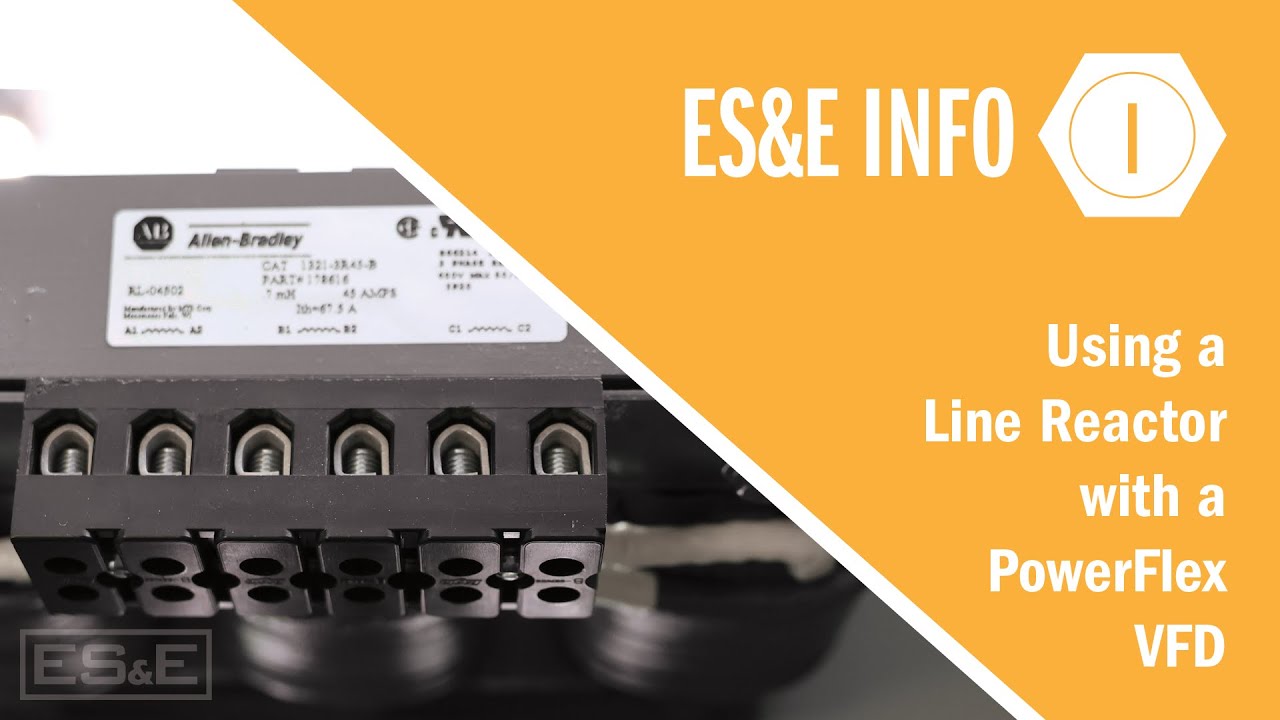
Using a Line Reactor with a PowerFlex VFD

Getting to Know The PowerFlex 525 - Connected Components Workbench

LRS vs VFD| What is Liquid Resistance Starter| What is VFD| Function of VFD| Motor Starting Method
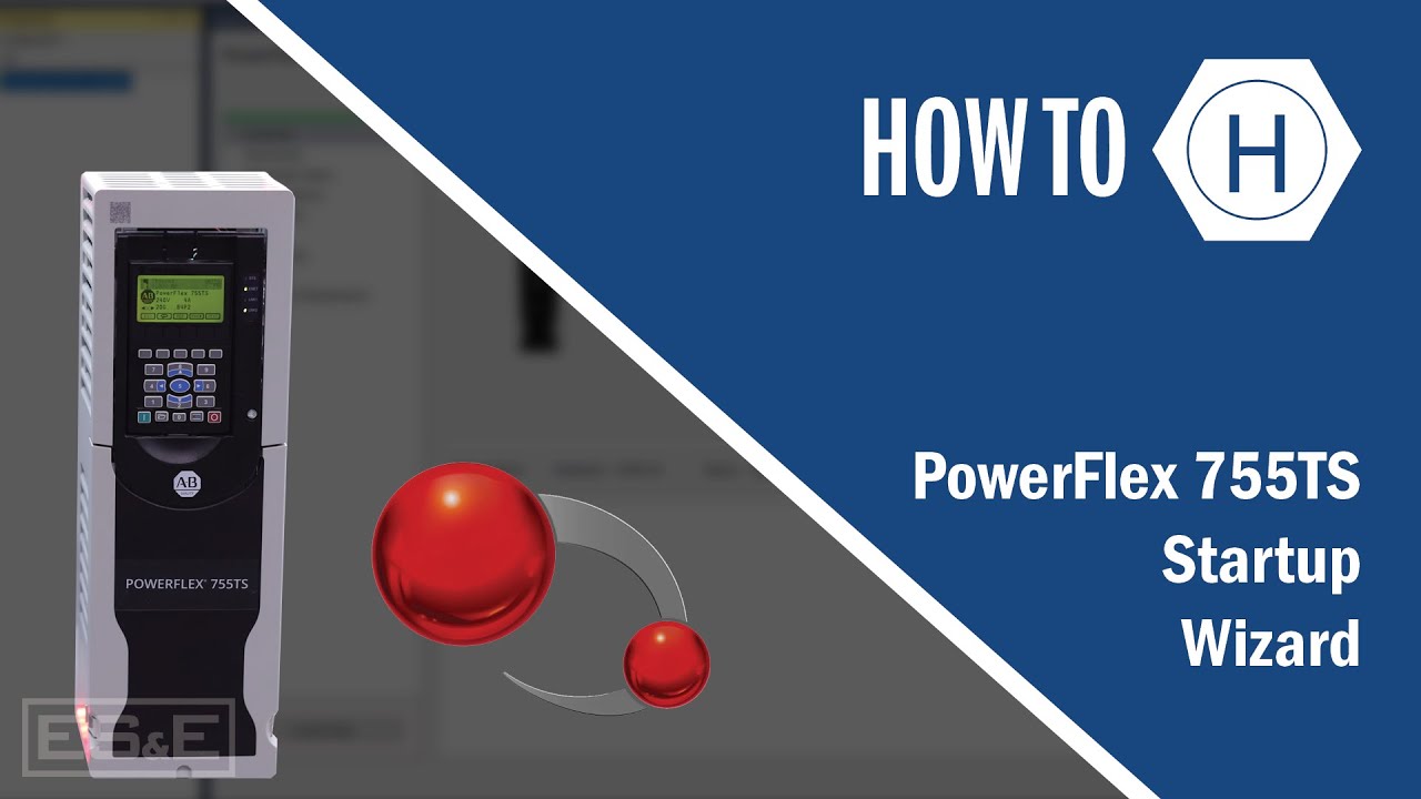
PowerFlex 755TS Startup Wizard

What is the Difference between VFD and Soft Starter?
5.0 / 5 (0 votes)
