Magnetic Circuits - B-H Relationship (Magnetization Curve)
Summary
TLDRIn this lecture, the BH relationship in magnetic circuit analysis is explored, detailing how magnetic field intensity (H) generates magnetic field density (B). The permeability (μ) of a material, which influences its magnetic field resistance, is discussed, with μ being the product of μ₀ (free space permeability) and μr (relative permeability). The lecture covers the linear and non-linear behaviors of B with respect to H, using the magnetization curve to illustrate the magnetic material's response to varying H. Practical applications, such as motor design and the importance of operating within the linear region of the magnetization curve for efficiency, are highlighted.
Takeaways
- 🧲 The BH relationship is fundamental in magnetic circuit analysis, where B (magnetic field density) is directly proportional to H (magnetic field intensity) through the permeability µ.
- 🌐 Permeability µ is the influence of a material on the magnetic field and is inversely proportional to the material's reluctance to magnetic field flow.
- 🔗 The permeability µ can be expressed as µ = µ₀ * µ_r, where µ₀ is the permeability of free space, and µ_r is the relative permeability of the medium.
- 🌌 µ₀, the permeability of free space, is a constant value of 4π × 10^-7 H/m.
- 🛠 In electrical machines, a high µ_r value implies that a small electric current can produce a large magnetic field density, which is crucial for efficient operation.
- 🔋 The magnetic field intensity H can also be referred to as the magnetic field excitation, which is the driving force behind establishing a magnetic field.
- 🔗 Ampere's Law is applied in magnetic circuits to relate the total ampere turns to the magnetic field intensity and permeability.
- 📉 The BH relationship for non-magnetic materials like air, aluminum, and copper is linear with a slope equal to the permeability of free space µ₀.
- 📈 For magnetic materials, the BH relationship is initially linear but becomes non-linear at higher magnetic field intensities due to saturation effects.
- 🔧 The shape of the magnetization curve explains the behavior of magnetic materials under varying magnetic field intensities, showing linearity at low fields and saturation at high fields.
- ⚙️ In the design of electrical machines, it's important to operate within the linear region of the magnetization curve to ensure efficiency and avoid excessive current draw.
Q & A
What is the BH relationship in magnetic circuits?
-The BH relationship refers to the relationship where the magnetic field intensity H produces a magnetic field density B in any medium. It is expressed as B equals to μ times H, where μ is the permeability of the medium.
What is the unit of magnetic field density B?
-The unit of magnetic field density B is weber per meter squared (Wb/m²).
How is permeability (μ) related to the reluctance of a material to the magnetic field?
-Permeability (μ) is inversely proportional to the reluctance of the material to the magnetic field. High permeability means low reluctance, indicating the material offers less resistance to the magnetic field.
What is the permeability of free space (μ₀) and its unit?
-The permeability of free space (μ₀) is defined as 4 times pi times 10 to the power of -7 henry per meter (H/m).
What is relative permeability (μ_r) and what does its value imply for a material?
-Relative permeability (μ_r) is a dimensionless quantity that represents the ability of a material to support the formation of a magnetic field compared to the ability of free space. A high μ_r value implies that a small electric current can produce a large amount of magnetic field density in the material.
How does the BH relationship change for non-magnetic materials?
-For non-magnetic materials like air, aluminum, plastic, wood, and copper, the relative permeability (μ_r) is unity, so the permeability (μ) equals μ₀, and the magnetic field density B equals μ₀ times H.
What is the significance of the magnetizing current (i) in the BH relationship?
-The magnetizing current (i) is the variable used to produce the BH relationship and is used to excite and establish the magnetic field density. It is a key factor in determining the magnetic field intensity H and, consequently, the magnetic field density B.
What is the shape of the magnetization curve for magnetic materials, and what does it indicate?
-The magnetization curve for magnetic materials shows an almost linear increase in magnetic field density B at low magnetic field intensity H, but becomes non-linear at higher values of H, indicating the onset of saturation where the material's permeability decreases.
What happens to the magnetic dipoles in a material when the magnetizing current is increased?
-As the magnetizing current is increased, the magnetic field intensity also increases, causing more dipoles to align with the magnetic field, which in turn increases the magnetic field density B.
Why is it important for designers to keep the operating points within the linear region of the magnetization curve?
-Designers aim to keep the operating points within the linear region of the magnetization curve to avoid the non-linear or saturation region, which requires too much current to achieve only a small increase in magnetic field density, leading to inefficiency and unnecessary losses.
How does an AC source affect the magnetization curve in a magnetic circuit?
-When an AC source is applied to a magnetic circuit, the full cycle of the magnetization curve, including both positive and negative sides, is repeated multiple times per second depending on the system frequency, such as 60 times per second for a 60 Hz system.
Outlines

此内容仅限付费用户访问。 请升级后访问。
立即升级Mindmap

此内容仅限付费用户访问。 请升级后访问。
立即升级Keywords

此内容仅限付费用户访问。 请升级后访问。
立即升级Highlights

此内容仅限付费用户访问。 请升级后访问。
立即升级Transcripts

此内容仅限付费用户访问。 请升级后访问。
立即升级浏览更多相关视频
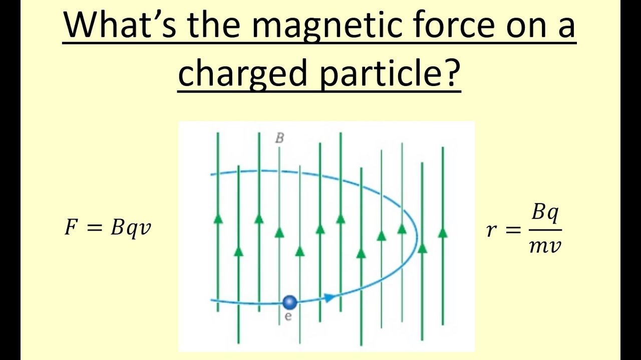
12.06 What affects the curvature of charged particles in a magnetic field?

AULA 1 B MÁQUINAS ELÉTRICAS 1 ELETROMAGNETISMO

Important Terms in Magnetic Circuit

Listrik Magnet 13.4 Elektrodinamika Induksi Elektromagnetik Hukum Faraday
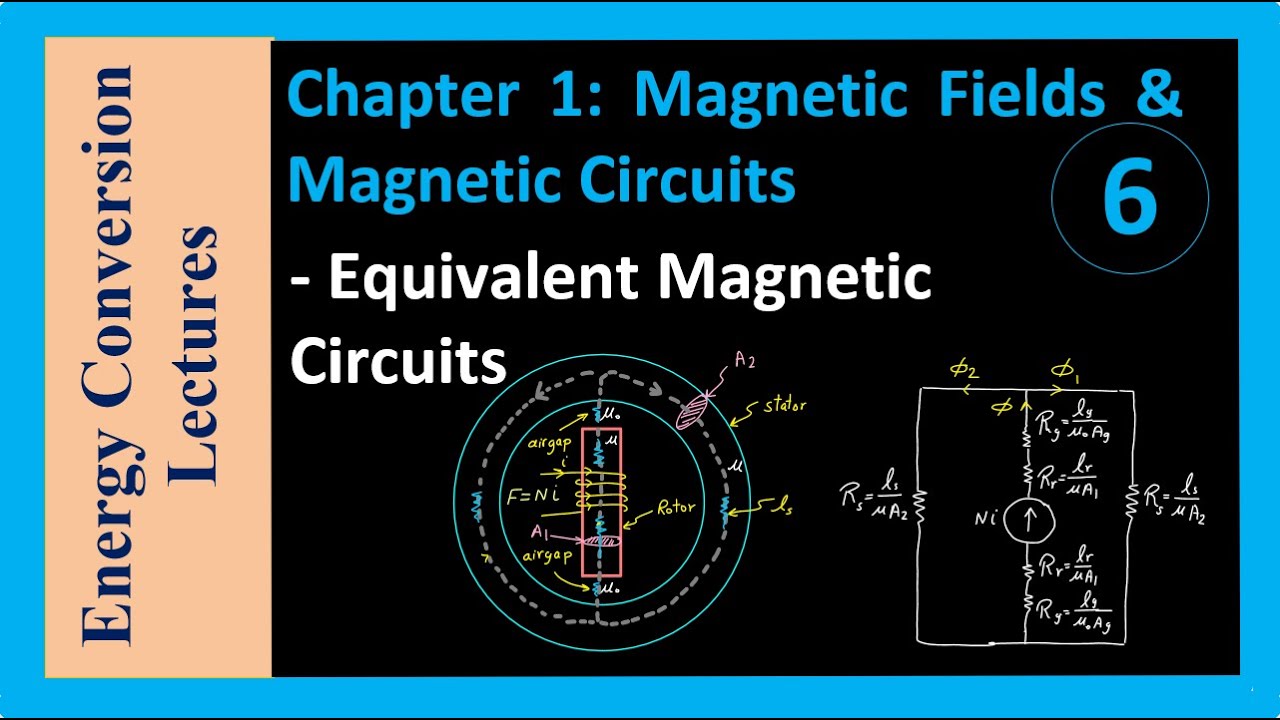
Magnetic Circuits - Equivalent Magnetic Circuits

GCSE Physics - Motor Effect #79
5.0 / 5 (0 votes)
