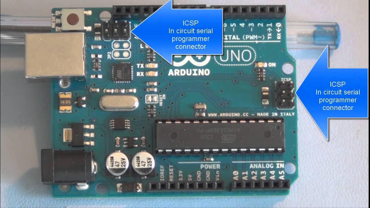
Arduino Uno - Pins Overview
Summary
TLDRThis video offers an in-depth exploration of the Arduino Uno board's pins, focusing on their functions and applications. It explains the importance of grounding, powering options, and the use of digital and analog pins for reading and controlling components. The script also covers PWM for analog control and the use of interrupts for efficient programming. Additionally, it introduces communication protocols like UART, SPI, and I2C for advanced data transfer between devices, providing a comprehensive guide for beginners and enthusiasts alike.
Takeaways
- 😀 The video provides an overview of the pins on an Arduino Uno board, with explanations applicable to most Arduino boards.
- 🔌 Ground pins are crucial for establishing a common reference point for voltage measurements across a circuit.
- 🔋 Power pins on the Arduino Uno board allow for external power sources and powering other components, with options including USB and a DC power jack.
- ⚡ The 'VIN' pin can be used to supply 7 to 12 volts to the board, and must be used with the ground pin for proper connection.
- 🔢 Digital pins (0-13) are used for reading data from sensors and controlling actuators, operating between 0 and 5 volts.
- 🛠 Before using a digital pin, it must be configured as either an input or output mode, which determines whether it reads or writes data.
- 📶 Some digital pins support PWM (Pulse Width Modulation), allowing for control over the voltage output for components like LEDs.
- 🔄 Interrupt pins (2 and 3) can trigger specific functions when an event occurs, without the need for continuous polling in the code.
- 📡 Analog pins (A0-A5) read continuous values, such as from a potentiometer, converting analog voltages into digital values for the Arduino to process.
- 🔄 Analog pins can also be used as digital pins, but without PWM functionality, by setting the appropriate mode in the Arduino program.
- 🔗 Communication protocols like UART, SPI, and I2C allow for complex data transfer between the Arduino and other devices or components.
Q & A
What is the primary purpose of the ground pins on an Arduino Uno board?
-The primary purpose of the ground pins is to provide a common reference point for all voltage measurements in a circuit, ensuring that all components are correctly linked to the ground and that voltages can be compared and measured accurately.
How can the Arduino Uno board be powered?
-The Arduino Uno board can be powered in two ways: through a USB cable connected to a computer, or through an external source using the DC power jack with a 7 to 12 volt supply.
What is the significance of having a common ground in a circuit?
-A common ground is essential for accurate voltage measurements, as it ensures that all voltages in the circuit can be compared against the same reference point. Without a common ground, it's impossible to determine the relative voltages across different parts of the circuit.
What are the two types of power pins on the Arduino Uno board and their functions?
-The two types of power pins are: 1) Pins that allow the Arduino board to be powered from an external source, and 2) Pins that enable the Arduino board to power external components.
How do PWM (Pulse Width Modulation) pins work on an Arduino Uno board?
-PWM pins work by creating a pulse that runs at a given frequency and varies the duty cycle, which is the percentage of time the pulse is in the high state. This produces an average voltage output that can be used to control the intensity of components like LEDs.
Which pins on the Arduino Uno board are compatible with PWM functionality?
-The pins compatible with PWM functionality on the Arduino Uno board are 3, 5, 6, 9, 10, and 11.
What is the purpose of the analog pins on an Arduino Uno board?
-The analog pins are used to read values from components that provide a range of values, such as a potentiometer, rather than just binary on/off states. They can read voltage levels and convert them into digital values that the Arduino can process.
How many analog pins are there on an Arduino Uno board and what are their identifiers?
-There are six analog pins on an Arduino Uno board, identified as A0 to A5.
What are the three main communication protocols available for use with an Arduino Uno board?
-The three main communication protocols available for use with an Arduino Uno board are UART, SPI, and I2C.
What are the functions of the UART pins on the Arduino Uno board?
-The UART pins, labeled RX (Reception) and TX (Transmission), are used for serial communication between the Arduino board and a computer or other devices. They allow for the transfer of data in a bi-directional manner.
How can analog pins be used as digital pins on an Arduino Uno board?
-Analog pins can be used as digital pins by setting their mode to input or output in the Arduino program's setup function. This allows the use of digital read or write functions for binary state control, but without PWM functionality.
Outlines

此内容仅限付费用户访问。 请升级后访问。
立即升级Mindmap

此内容仅限付费用户访问。 请升级后访问。
立即升级Keywords

此内容仅限付费用户访问。 请升级后访问。
立即升级Highlights

此内容仅限付费用户访问。 请升级后访问。
立即升级Transcripts

此内容仅限付费用户访问。 请升级后访问。
立即升级5.0 / 5 (0 votes)


