What are Branches, Nodes, and Loops with Series and Parallel Components? | Basic Electronics
Summary
TLDRThis tutorial delves into the fundamentals of basic circuits, focusing on branches, nodes, and loops. It explains that branches are two-terminal devices like resistors and capacitors, nodes are connection points with zero resistance, and loops are closed paths without crossing. The video further explores series and parallel configurations of resistors, detailing how to simplify circuits by calculating equivalent resistances, which is crucial for circuit analysis and understanding the behavior of more complex circuits.
Takeaways
- 🌟 Basic circuits involve understanding fundamental concepts such as branches, nodes, and loops, which are essential for analyzing more complex circuits.
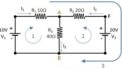
- 🔌 A branch is any two-terminal device, such as a voltage source, resistor, capacitor, or inductor, which is a fundamental component in circuits.
- 🔗 A node is a point where two or more electrical components are connected, and it's crucial for understanding how current flows through a circuit.
- 🔄 Loops are continuous paths in a circuit where current can flow without crossing itself, and they are important for applying Kirchhoff's laws.
- 🔍 Identifying nodes and branches is critical for setting up equations in circuit analysis, as they affect how voltage and current are distributed.
- 🔄 Series circuits have components connected end-to-end, sharing the same current through each component, which simplifies to a single equivalent resistance.
- 🔄 Parallel circuits have components connected across the same nodes, sharing the same voltage across each component, and their resistances combine differently than in series.
- ⚙️ Simplifying series resistors is straightforward by adding their resistances together to get the equivalent resistance.
- ⚙️ Simplifying parallel resistors involves a more complex calculation, typically using the reciprocal sum method to find the equivalent resistance.
- 📉 Placing resistors in series increases the overall resistance, while placing them in parallel decreases it, which is useful for controlling circuit resistance.
- 🔧 Understanding series and parallel configurations is fundamental for simplifying circuits and is a skill that becomes intuitive with practice.
Q & A
What are the fundamental concepts discussed in the video tutorial?
-The video tutorial discusses the fundamental concepts of branches, nodes, and loops in basic electrical circuits.
What is a branch in the context of electrical circuits?
-A branch is any two-terminal device in an electrical circuit, such as a voltage source, resistor, capacitor, or inductor.
How is a node defined in an electrical circuit?
-A node is defined as a point where two or more electrical components are connected together, assuming zero resistance between the terminals.
What is the significance of understanding nodes in circuit analysis?
-Understanding nodes is crucial because they are the points where components share a common connection, and they are essential for setting up equations in circuit analysis, especially when applying Kirchhoff's laws.
What is a loop in an electrical circuit?
-A loop is a closed conducting path in a circuit where current can flow without crossing itself or returning to the starting point through the same path.
Why is it important to distinguish between different types of loops in circuit analysis?
-It is important to distinguish between different types of loops because certain analysis methods, like mesh analysis, require loops that do not enclose other loops to apply Kirchhoff's Voltage Law correctly.
What is the difference between series and parallel connections in electrical circuits?
-In series connections, components share the same current and are connected end-to-end, sharing the same nodes exclusively. In parallel connections, components share the same voltage across them and are connected to the same two nodes, allowing different currents to flow through each component.
How can you simplify a series connection of resistors?
-You can simplify a series connection of resistors by adding their resistances together to get the equivalent resistance, as the current through each resistor in series is the same.
How can you calculate the equivalent resistance for two resistors connected in parallel?
-For two resistors in parallel, you calculate the equivalent resistance using the formula \( \frac{1}{R_{\text{equivalent}}} = \frac{1}{R_1} + \frac{1}{R_2} \), which simplifies to \( R_{\text{equivalent}} = \frac{R_1 \times R_2}{R_1 + R_2} \) for two resistors.
What is the effect of connecting resistors in series on the overall resistance?
-Connecting resistors in series increases the overall resistance because the equivalent resistance is the sum of the individual resistances.
What is the effect of connecting resistors in parallel on the overall resistance?
-Connecting resistors in parallel decreases the overall resistance because the equivalent resistance is lower than the lowest individual resistance.
Outlines

This section is available to paid users only. Please upgrade to access this part.
Upgrade NowMindmap

This section is available to paid users only. Please upgrade to access this part.
Upgrade NowKeywords

This section is available to paid users only. Please upgrade to access this part.
Upgrade NowHighlights

This section is available to paid users only. Please upgrade to access this part.
Upgrade NowTranscripts

This section is available to paid users only. Please upgrade to access this part.
Upgrade NowBrowse More Related Video

Electrical Engineering: Basic Laws (6 of 31) What are Nodes, Branches, and Loops?

Series and Parallel Circuits

Electric Circuits: Basics of the voltage and current laws.

Electrical Engineering: Ch 8: RC & RL Circuits (1 of 43) RC & RL Circuits Introduction

JavaScript DOM - Children, Parent & Sibling Nodes | Sigma Web Development Course - Tutorial #67

HUKUM II KIRCHHOFF
5.0 / 5 (0 votes)