555 Chip Explained - LED Blinker, Buzzer, Siren...

DiodeGoneWild
16 Feb 202416:57

Summary

TLDRThis video tutorial offers an in-depth introduction to the 555 oscillator chip, a staple in electronics for over 50 years. It explains the function of all eight pins and demonstrates how to create simple circuits like LED blinkers and beepers with varying frequencies. The video also covers the impact of different resistor and capacitor values on oscillation speed, introduces the concept of duty cycles, and explores the use of the chip's lesser-known pin five for unique applications. Viewers are guided through building oscillators with fixed and variable frequencies, offering a comprehensive foundation for beginners in circuit design.

Takeaways

  • πŸ˜€ The 555 oscillator chip is an essential component for beginners in electronics, commonly used for over 50 years.
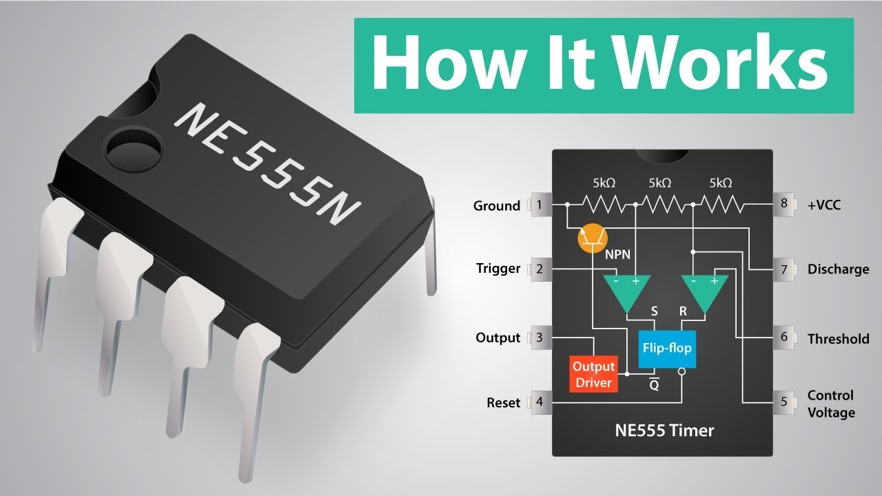
  • πŸ”Œ The 555 chip has 8 pins with pins 1 and 8 serving as the supply voltage connections, pin 1 being ground and pin 8 the positive supply.
  • πŸ”„ Pins 3 and 7 are the two main outputs of the 555 chip, functioning as switches controlled by internal transistors.
  • πŸ”© The 555 chip operates with two main inputs, pins 2 and 6, which control the flipping of the outputs based on voltage levels.
  • πŸ”„ An additional reset input can override the outputs, but is often left unconnected or connected to the positive supply to disable its effect.
  • πŸ”„ The 555 chip can be easily turned into an oscillator due to its inverting effect on the inputs and outputs.
  • πŸ’‘ By connecting LEDs to the outputs, one LED will light up when the output is low and the other when it's high, creating an alternating blink.
  • ⚑ The frequency of the oscillator can be adjusted by changing the values of the resistor and capacitor in the circuit.
  • πŸ”Š A beeper can be created using a small speaker with the 555 chip, requiring higher frequencies achieved by using lower capacitance values.
  • πŸ”„ Pin 5 of the 555 chip can be used to manipulate threshold values, influencing the frequency and duty cycle of the output.
  • πŸ”„ The duty cycle of the oscillator can be altered by using a potentiometer or by changing the resistor values, allowing for unequal blinking of LEDs.

Q & A

  • What is the 555 oscillator chip?

    -The 555 oscillator chip is a versatile integrated circuit used in various electronic applications, including the creation of oscillators, timers, and pulse generators. It has been in production for over 50 years and is often one of the first chips that beginners in electronics learn about.

  • How many pins does the 555 oscillator chip have?

    -The 555 oscillator chip has eight pins, each serving a specific function, such as supply voltage connections, outputs, and inputs.

  • What are the functions of pin 1 and pin 8 on the 555 chip?

    -Pin 1 is the ground pin, connected to 0 volts, and pin 8 is the positive supply voltage pin, typically receiving a voltage between plus 5 to +15 volts from a DC power supply or battery.

  • What are the two main outputs of the 555 chip?

    -The two main outputs of the 555 chip are pin 3 and pin 7. These outputs can be in two states, high or low, and are controlled by internal transistors acting as switches.

  • How do the inputs of the 555 chip affect the outputs?

    -The inputs of the 555 chip, specifically pins 2 and 6, control the state of the outputs. When the voltage at pin 2 goes below 1/3 of the supply voltage, the outputs flip up. When the voltage at pin 6 goes above 2/3 of the supply voltage, the outputs flip back down.

  • What is the purpose of the reset pin on the 555 chip?

    -The reset pin, when connected to 0 volts, overrides the other inputs and forces the outputs to flip down. It is often left unconnected or connected to the positive supply rail to disable its effect.

  • How can the frequency of a 555 oscillator circuit be adjusted?

    -The frequency of a 555 oscillator circuit can be adjusted by changing the values of the resistor and capacitor used in the feedback loop. Higher resistance or capacitance results in a slower frequency, while lower values result in a faster frequency.

  • What is the function of pin 5 on the 555 chip?

    -Pin 5 on the 555 chip is connected to the internal resistive divider and can be used to manipulate the threshold values for pins 6 and 2, which affects the frequency and duty cycle of the output. It can also be used as a filter to prevent noise on the supply rail from affecting the threshold values.

  • How can the 555 chip be used to create a variable frequency oscillator?

    -A variable frequency oscillator can be created by adding a potentiometer in series with the resistor in the feedback loop of the 555 circuit. Adjusting the potentiometer changes the resistance, which in turn changes the frequency of the oscillator.

  • What is the purpose of connecting a capacitor to the supply rails in a 555 circuit?

    -Connecting a capacitor between the positive and negative supply rails, often referred to as decoupling or bypass capacitor, helps stabilize the circuit by filtering out any noise or fluctuations in the power supply. It is typically a polarized electrolytic capacitor with a value ranging from 100 to 1000 microfarads.

  • How can the 555 chip be used to create a beeper circuit?

    -A beeper circuit can be created by connecting a small speaker to the output of a 555 oscillator circuit. The frequency of the oscillator needs to be high enough for the speaker to produce an audible sound. Capacitors with lower values are used to achieve higher frequencies.

  • What is the effect of connecting a diode in the oscillator resistor of a 555 circuit?

    -Connecting a diode in the oscillator resistor allows the LEDs to blink unequally, changing the duty cycle of the oscillator. Without the diode, the duty cycle is always 50% or higher, but with the diode, any duty cycle can be achieved depending on the ratio of the resistors.

Outlines

00:00

πŸ”Œ Introduction to the 555 Oscillator Chip

This paragraph introduces the 555 oscillator chip, a common component in electronics, particularly for beginners. It explains the chip's eight pins, including the supply voltage pins (1 and 8), and the two output pins (3 and 7) that function as switches controlled by internal transistors. The paragraph also covers the two main input pins (2 and 6) that determine when the outputs flip based on voltage levels, as well as the less commonly used reset pin. The 555 chip's oscillator function is highlighted, demonstrating how it can create an oscillating circuit with the right components, such as resistors and capacitors, to control the frequency.

05:00

πŸ’‘ Building an LED Blinker Circuit with the 555 Chip

The second paragraph delves into constructing an LED blinker circuit using the 555 chip. It describes how to connect LEDs to the chip's outputs, with one LED lighting up when the output is low and the other when it's high, creating an alternating blinking effect. The importance of stabilizing the circuit with a capacitor across the supply rails is emphasized, along with the impact of varying resistor and capacitor values on the blink rate. The paragraph also explains the role of the internal resistive divider and pin 5 in setting threshold voltages for the inputs, and how manipulating these can influence the circuit's frequency and duty cycle.

10:03

πŸ”Š Creating a Variable Frequency Oscillator and Beeper

This paragraph discusses creating a variable frequency oscillator using a potentiometer to adjust the blink rate of an LED blinker circuit. It then transitions to building a beeper circuit with a small speaker, explaining the need for higher frequencies and the use of different capacitor values to achieve this. The speaker is connected via a capacitor to receive the AC signal, not DC, and the frequency can be adjusted to produce different sounds, from clicks to buzzes. The paragraph also touches on experimenting with pin 5, using it to control a blinking LED and create a siren effect.

15:05

πŸ”„ Advanced Oscillator Techniques and Applications

The final paragraph covers advanced techniques for the 555 oscillator, such as using pin 7 for feedback to create a more stable oscillator, adjusting the duty cycle with resistor values, and using a diode to create unequal on-off times for the LEDs. It also mentions the possibility of using the 555 chip in non-oscillating circuits, like a flip-flop or monostable timer, and hints at further exploration of these topics in future videos. The paragraph concludes with an invitation for viewers to support the channel and a mention of a bonus circuit, encouraging continued interest and engagement.

Mindmap

Keywords

πŸ’‘555 Oscillator Chip

The 555 oscillator chip is a versatile integrated circuit used for generating accurate and stable time delays or oscillation. In the video, it is the central component around which various circuits are built, such as LED blinkers and beepers. The script explains its pin functions and how it can be configured to create different types of oscillators, emphasizing its importance in the theme of building electronic circuits.

πŸ’‘LED Blinker

An LED blinker is a simple electronic circuit that causes an LED to turn on and off at regular intervals. The video script describes how to create an LED blinker using the 555 oscillator chip, illustrating the practical application of the chip in a beginner-friendly project. The blinker serves as an example of how the 555 chip can be used to generate time-based signals.

πŸ’‘Beeper

A beeper in the context of the video refers to a circuit that produces sound pulses using the 555 oscillator chip. The script mentions creating a beeper with two frequencies, demonstrating the chip's capability to generate audible signals for various applications. The beeper exemplifies the audio output potential of the 555 chip.

πŸ’‘Variable Frequency

Variable frequency refers to the ability to change the rate of oscillation in a circuit. The video script explains how to modify the frequency of the 555 oscillator circuit by altering the values of the resistor and capacitor, which is key for creating circuits with adjustable speed or pitch, such as the variable frequency blinker and beeper.

πŸ’‘Pin Functions

Pin functions describe the purpose of each pin on the 555 oscillator chip. The script provides a detailed explanation of the eight pins, including supply voltage pins, output pins, and input pins, which are crucial for understanding how the chip operates within the circuits discussed in the video.

πŸ’‘Logic Chip

A logic chip, as mentioned in the script, is a type of integrated circuit that performs logical operations and can have outputs in only two states, typically represented as 0 (low) and 1 (high). The 555 chip is described as a logic chip, emphasizing its digital nature and how its outputs are controlled by internal transistors acting as switches.

πŸ’‘Oscillator

An oscillator is a circuit that generates a repetitive signal, often a square wave. The video script explains how the 555 chip can be configured as an oscillator by providing feedback from the output to the input through a resistor and capacitor, which is fundamental to the operation of the circuits presented.

πŸ’‘Duty Cycle

Duty cycle refers to the ratio of the time a signal is active (high) compared to the total period of the signal. The script discusses adjusting the duty cycle of the 555 oscillator by modifying resistor values or using a diode, which affects how long the output is high versus low, impacting the behavior of the LED blinker.

πŸ’‘Resistor

A resistor is a passive component that opposes the flow of electric current in a circuit. The video script frequently mentions resistors, explaining how their values affect the frequency and duty cycle of the 555 oscillator circuits, such as in the LED blinker and beeper examples.

πŸ’‘Capacitor

A capacitor is a component that stores electrical energy and can smooth, filter, or delay voltage changes in a circuit. The script describes using capacitors in conjunction with resistors to determine the frequency of the 555 oscillator circuits, as well as to create stable operating conditions.

πŸ’‘Potentiometer

A potentiometer is a type of resistor with a sliding contact that allows for continuous adjustment of resistance. The video script describes adding a potentiometer to the oscillator circuit to create a variable frequency, demonstrating a practical way to adjust the speed of the circuit manually.

πŸ’‘Internal Resistive Divider

An internal resistive divider in the context of the 555 chip is a network of resistors within the chip that sets the voltage threshold levels for the input pins. The script explains how this divider creates the 1/3 and 2/3 supply voltage levels that determine when the chip's outputs flip, which is essential for the operation of the oscillator circuits.

πŸ’‘Output Pin

Output pins on the 555 chip, such as pin 3 and pin 7, are used to provide the signal from the chip to external components like LEDs or speakers. The script discusses how these pins can be configured to drive different types of loads and how their behavior can be influenced by the circuit design.

Highlights

Introduction to the 555 oscillator chip, a common component for beginners in electronics.

Explanation of the 8 pins of the 555 chip, including supply voltage pins 1 and 8.

Description of the two outputs, pin 3 and pin 7, and their binary switching behavior.

Input pins 2 and 6 control the flip of the outputs based on voltage levels.

The reset pin's function and its priority over the other inputs.

Building a simple oscillator using the 555 chip with an inverting effect on the pins.

Use of a resistor and capacitor to control the frequency of the oscillator.

Connecting LEDs to the oscillator to visually indicate the blink rate.

The role of pin 5 in adjusting threshold values and its common applications.

Demonstration of changing the blink rate by altering resistor and capacitor values.

Construction of a variable frequency oscillator using a potentiometer.

Creating a beeper circuit with the 555 chip and adjusting frequency for audible sound.

Experimentation with pin 5 to control the blinking of an LED integrated into the circuit.

Use of pin 7 for oscillator feedback and the need for a pullup resistor.

Adjusting the duty cycle of the oscillator by manipulating resistor values.

Implications of using extremely low or high resistances in the oscillator circuit.

Introduction of non-oscillating 555 chip circuits like the flip-flop and monostable circuits.

Invitation to support the channel for further detailed exploration of 555 chip applications.

Transcripts

play00:00

so today a video for beginners

play00:02

explaining a 555 oscillator chip and

play00:04

some simple circuits with it like an LED

play00:07

blinker and a beeper or even a beeper

play00:10

with two frequencies and a variable

play00:12

frequency blinker I will show the

play00:14

schematics of these circuits but first

play00:17

let's explain what all the pins of the

play00:18

555 oscillator chip do a 555 oscillator

play00:22

chip has eight pins and in reality it

play00:25

looks like this and there are different

play00:27

versions from many different makers and

play00:30

they're making this one for over 50

play00:32

years now and it's a very common chip

play00:35

and for beginners in electronics very

play00:36

often the first chip they learn about

play00:39

first let's take a look at the pin one

play00:41

and eight these are the supply voltage

play00:44

pins pin one is the ground connected to

play00:47

0 volts and pin 8 is the positive Supply

play00:50

voltage and it's typically from plus 5

play00:52

to + 15 volts from a DC power supply or

play00:56

from a battery and then it has two

play00:58

outputs pin three and pin 7 and this is

play01:01

a logic chip not an analog chip so the

play01:04

outputs can be just in two states

play01:06

nothing in between and the outputs are

play01:09

switched by internal transistors in it

play01:11

which you can imagine for Simplicity as

play01:13

switches the pin three can be either

play01:15

switched to the Z volt rail the ground

play01:19

or to the positive Supply

play01:21

Rail and then there is another output

play01:24

pin 7 called mysteriously discharge

play01:27

acting sort of similar as this one but

play01:29

it only switches to the Zer volt rail or

play01:32

to nothing and they of course

play01:34

synchronized they always flip at the

play01:37

same time but this one connected to the

play01:39

pin 7 only switches to the ground not to

play01:42

the positive of course in reality this

play01:44

output is an npn transistor with an open

play01:47

collector but let's not make it too

play01:49

complicated so these two pins are the

play01:52

outputs they work like switches but what

play01:54

makes these switches flip they flip

play01:57

based on what happens at the inputs the

play01:59

555 chip has two main inputs the pins 2

play02:03

and six plus an additional input reset

play02:07

the output skan flip based on what

play02:09

happens at the inputs first let's take a

play02:11

look at this input pin two when the

play02:14

voltage at this input goes below 1/3 of

play02:17

the supply voltage the switches flip up

play02:20

this output gets the supply voltage on

play02:22

it and this output is disconnected now

play02:25

they basically flipped into the upper

play02:27

position here so now we flip the

play02:30

switches up and how do we flip them back

play02:32

down when the voltage at this input pin

play02:35

six goes above 2/3 of the supply voltage

play02:39

they flip back down so they're again in

play02:42

this

play02:42

position both outputs connected to the Z

play02:46

volt rail or ground so one input flips

play02:49

the outputs up when the voltage goes low

play02:51

enough and one flips them down when the

play02:54

voltage goes high enough and in most

play02:56

oscillator circuits these two inputs pin

play02:59

six and and pin two are connected with

play03:02

each other so they basically work as

play03:04

just one input which can flip the

play03:05

outputs both up and down and there is

play03:08

one more input which is not used very

play03:10

often is the reset pin and this flips

play03:13

the outputs down when it's connected to

play03:15

0 volts but in most cases it's unused

play03:18

you can leave the pin unconnected but

play03:19

it's better to actually connect it to

play03:22

the positive Supply rail to basically

play03:25

disable it so it has no effect and of

play03:28

course the inputs have some priority is

play03:30

the reset input has the highest priority

play03:32

so if this is connected to 0 volts it

play03:34

flips the outputs down and it doesn't

play03:37

care about the input six and two and

play03:39

then input two has a lower priority and

play03:41

the input six the lowest one if you for

play03:44

example pull pin two under 1/3 of the

play03:47

supply voltage and pin six

play03:49

simultaneously above 2/3 of the supply

play03:52

voltage the pin two has a priority end

play03:55

so the outputs flip up but this never

play03:57

happens when these two are connected

play03:59

with each other there of course but now

play04:01

let's build a very simple oscillator out

play04:03

of it the pins have an inverting effect

play04:05

so it's easy to turn it into an

play04:07

oscillator when this pair of penis is

play04:09

pulled higher the output goes low and

play04:12

when it's pulled lower the output goes

play04:14

high it's inverting so it can form an

play04:16

oscillator when basically the output

play04:18

goes back into the inputs but of course

play04:21

it shouldn't be connected directly it

play04:23

has to go via a

play04:25

resistor now with this feedback it's

play04:28

basically an oscillator but it would

play04:29

oate extremely fast so we have to make

play04:32

it slower by adding a capacitor the

play04:35

inputs and the here the capacitance the

play04:38

slower it is the lower the frequency of

play04:40

the oscillator and also the higher the

play04:43

resistance of this resistor the slower

play04:45

the oscillator is or its output

play04:47

frequency is lower now the circuit

play04:49

oscillates but we can't see it because

play04:51

there is no indication so let's connect

play04:54

some LEDs to it he connected a pair of

play04:57

LEDs this one lights up when the outputs

play05:00

are low and the current goes from the

play05:02

positive Supply rail through this

play05:04

led into this output and into the Z volt

play05:08

Rail and when this output is high the

play05:11

current goes from the supply rail

play05:13

through the

play05:14

output through this LED and to the Z

play05:18

volt rail so it's always one LED on and

play05:21

the other one off I gave the component

play05:23

some values these resistors are 560 ohms

play05:27

it's not critical it can be for example

play05:29

one kiloohm as well this resistor is 470

play05:33

KMS and this capacitor is 1 microfarad

play05:35

ceramic capacitor and the circuit looks

play05:39

like this the LEDs are alternately

play05:41

blinking but of course it's a good

play05:43

practice as you can see to connect a

play05:45

capacitor to the supply rails between

play05:48

the positive and the negative like this

play05:52

for stability of the circuit typically

play05:55

this capacitor is from 100 microfarads

play05:57

to 1,000 microfarads and it's an

play06:00

electrolytic capacitor which is

play06:02

polarized and it's negative for a z volt

play06:05

terminal it's marked using this stripe

play06:07

with a minus symbol which goes to the

play06:10

first pin of this chip and how this

play06:13

circuit works when the output is high it

play06:16

basically charges via this resistor this

play06:19

capacitor and it's charged until it

play06:21

reaches 2/3 of the supply voltage and

play06:24

then it flips and this output is low and

play06:27

Via this resistor it discharges this cap

play06:30

until it reaches 1/3 of the supply

play06:32

voltage and then the output flips back

play06:35

too high and it keeps repeating so for

play06:38

example our supply voltage is 6 Vols of

play06:41

battery let's say so the voltage at this

play06:43

capacitor and the inputs looks like this

play06:47

the capacitor charges to 2/3 of the

play06:50

supply voltage and this charges to 1/3

play06:54

and this keeps

play06:56

repeating and the output pin three goes

play06:59

like this 6 Vol 0 Vol 6 Vol 0 Vols while

play07:05

the inputs are going between 2 volts and

play07:07

4 Vols but of course if the supply

play07:10

voltage was 12 volts it would be going

play07:13

between 4 volts and 8 volts the

play07:17

threshold levels always depend on the

play07:18

supply voltage and these threshold

play07:21

levels are created by an internal

play07:23

resistive divider in the chip made of

play07:26

three

play07:28

resistors and there is one last

play07:30

mysterious pin pin five and this one is

play07:32

actually connected to this divider to

play07:35

this spot on it and this spot is

play07:37

actually used as the threshold value for

play07:40

the pin six and the voltage on this spot

play07:43

is used as the threshold voltage for the

play07:45

pin Two And the pin five is very often

play07:47

unused or it can be connected via a

play07:50

capacitor to the Z volt rail as some

play07:52

sort of a filter so the threshold values

play07:54

are not influenced by the noise on the

play07:56

supply Rail and this capacitor typically

play07:59

is 100 nanofarad ceramic or this pin can

play08:03

also be used to manipulate the threshold

play08:05

values you can externally change the

play08:07

voltage on this pin to change the

play08:09

threshold values for the pin 6 and two

play08:12

which in an oscillator influences the

play08:14

frequency and Dy cycle at the output but

play08:17

let's leave this spin for now and let's

play08:19

go back to our blinker and let's try to

play08:21

change the speed of it by changing the

play08:23

values of these two components when I

play08:25

replace the 470 kohm resistor using 1

play08:28

Mega ohm resistor it's blinking slower

play08:32

the higher the resistance the slower it

play08:34

is the lower the

play08:35

frequency and now I have an 82 km

play08:38

resistor which is much lower resistance

play08:40

so it should be much faster now and it's

play08:43

blinking quite fast now let's replace

play08:46

the 1 microfarad capacitor in the

play08:48

oscillator using a 10 microfarad

play08:50

capacitor a higher capacitance should

play08:52

make it slower again and this one is

play08:54

electrolytic it's polarized so this pin

play08:56

has to go to the negative or 0 volt rail

play08:59

and pin one of the chip let's replace

play09:02

the capacitor and higher capacitance

play09:05

makes it run slower the frequency is

play09:07

lower now let's make an oscillator with

play09:10

a variable frequency I added a

play09:12

potentiometer in series with the

play09:14

resistor in the oscillator here you can

play09:16

see the potentiometer in the circuit and

play09:19

by turning the potentiometer I can

play09:21

change the

play09:23

speed it's getting

play09:28

faster and even

play09:34

faster and the slower

play09:37

again and here's the schematic of it and

play09:40

now let's try to build a beeper I will

play09:42

use this small speaker for it and the

play09:45

frequency has to be much higher for this

play09:47

I will replace the one microfarad

play09:48

capacitor using a 100 nanofarad

play09:51

capacitor a lower capacitance means a

play09:53

higher frequency and it can be even

play09:55

higher until it's so fast you can't even

play09:58

see it

play10:02

so I added a speaker to the circuit and

play10:05

speakers are connected to the output via

play10:07

a capacitor not directly so they only

play10:09

get thec voltage not the DC and the

play10:12

frequency is quite low so it's clicking

play10:15

and when I increase

play10:23

it it's

play10:24

buzzing and to get the frequency even

play10:27

higher let's replace this one 100

play10:29

nanofarad capacitor using a 10 nanofarad

play10:35

capacitor and now it's higher and I can

play10:38

again adjust

play10:43

it it works

play10:45

[Music]

play10:55

nicely now let's experiment with the pin

play10:57

five who was a kid my favorite use for

play11:00

it was to connect a blinking LED to it

play11:03

it's an LED with a blinker built into it

play11:06

and this blinking Le when connected to a

play11:08

power supply just via resistor blinks on

play11:11

its own thanks to its built-in blinking

play11:13

circuitry now let's try to connect it to

play11:15

the pin five it will go from the pin

play11:18

five to the Z volt Rail and always in

play11:21

LEDs the longer pin is theod or the

play11:24

positive so the longer pin goes to the

play11:26

pin five let's turn it on

play11:29

and let's add the

play11:33

El and we have a 2 siren and the is

play11:38

blinking by the

play11:42

[Music]

play11:51

dimly he removed these eles and now we

play11:55

have a 2o

play11:57

siren

play12:02

[Music]

play12:05

and of course it's schematic and adding

play12:08

a resistor going from the positive to

play12:10

the pin five and the LED makes it blink

play12:13

brighter and changes the behavior a

play12:15

[Music]

play12:24

bit and now let's go back from the

play12:26

Beeper to the blinker to be able to

play12:28

demonstrate how to use the pin 7 he was

play12:32

previously connecting the oscillator

play12:33

resistor from the pin 3 to the pin two

play12:36

which makes the circuit a bit simpler it

play12:38

saves one resistor but the feedback for

play12:41

the oscillator can also go from the pin

play12:43

seven to the pin 2 and six and this is

play12:46

actually the recommended way of doing it

play12:48

because if the resistor goes from the

play12:50

pin three the oscillator might be

play12:52

influenced by the load so it might be

play12:55

better to use the output pin three just

play12:57

for the load and the PIN 7 for the

play12:59

oscillator but because the output 7 only

play13:02

switches to the0 volt rail not to the

play13:04

positive rail it requires an additional

play13:07

pullup resistor so this is the main

play13:09

oscillator resistor and this is the

play13:11

pullup resistor and when you want to 50%

play13:13

R the cycle which means the on time for

play13:16

each LED is roughly equal you're using a

play13:18

much lower resistance for the pullup

play13:20

resistor and a much higher resistance

play13:22

for the oscillator resistor in this

play13:25

example I'm using just 10 KMS here and

play13:28

400 20 KS here and because this one is

play13:30

much higher than this one they blink

play13:33

about equally but when this one has a

play13:35

higher value in this example 470 khms

play13:39

and this one at just 82 khms they are

play13:41

blinking

play13:42

unequally the green LED always stays on

play13:45

much longer than the red one and with a

play13:48

4.7 microfarad capacitor in the

play13:51

oscillator which makes it

play13:56

slower but again uny this resistance is

play13:58

much lower than this one the LEDs will

play14:01

blink

play14:03

unequally and also regarding the

play14:05

resistors in the oscillator it's not

play14:06

recommended to use extremely low or

play14:08

extremely high resistances the lowest

play14:11

should be something like 4.7 KS and the

play14:14

highest about 2.2 MGA very low

play14:17

resistances loads the chip too much and

play14:20

with very high resistances the leakage

play14:22

currents show up and this recommendation

play14:24

applies to both resistors here or the

play14:27

resistor here in the previous examples

play14:30

and now I went back to these values

play14:32

which make an equally blinking

play14:33

oscillator because this one is much

play14:35

lower than this one and now let's

play14:37

demonstrate the pin 4 let's disconnect

play14:40

it from the positive and connect it to

play14:42

the Z volt raail and when I do this it

play14:46

will stop the oscillator now the output

play14:49

stay low so the red LED is always on and

play14:52

the current goes like this and of course

play14:55

when these two resistors are used in the

play14:57

oscillator the capacitor's charging via

play14:59

the series combination of both resistors

play15:02

but it's discharging just via this

play15:04

resistor the capacitor's charging from

play15:06

the positive rail through the two

play15:09

resistors like this and it's

play15:13

discharging theyjust this resistor and

play15:15

into the pin seven and now the schematic

play15:18

is a proper mass and one more example

play15:21

circuit with an added diode on this

play15:24

resistor in the oscillator now this

play15:26

capacitor is charging just via this

play15:29

resistor instead of the series

play15:30

combination and it's discharging via

play15:33

this

play15:34

resistor and this allows the LEDs to

play15:36

Blink unequally the other way now the

play15:38

red one stays on longer in other words

play15:41

the duty cycle of the oscillator can now

play15:43

be below 50% instead of over

play15:46

50% now the waveform is like this when

play15:49

the green one stayed on longer the

play15:52

waveform was like

play15:54

this with the diode you can produce any

play15:57

duty cycle basically depending just on

play15:59

the ratio of these resistors but without

play16:01

the diode the duty cycle is always 50%

play16:04

or higher and the 555 oscillator can

play16:06

basically produce square waves for many

play16:09

different purposes from a fraction of a

play16:11

Herz up to several 100 KZ and there are

play16:14

also some circuits with a 555 chip that

play16:16

are not oscillating for example a bable

play16:19

circuit which can flip between two LEDs

play16:23

or can be used for just one to turn

play16:25

something on and off using push buttons

play16:28

or a mono stable circuit basically a

play16:31

timer but this video is getting too long

play16:33

so if you're interested you can talk

play16:35

about this in more detail in another

play16:37

episode so that's it and if you like my

play16:39

videos please consider supporting this

play16:41

channel on patreon using the thanks

play16:43

button and subscribing and big thanks to

play16:46

all of you who already support me

play16:48

because this channel couldn't exist

play16:49

without

play16:51

you and a bonus

play16:55

circuit

Rate This
β˜…
β˜…
β˜…
β˜…
β˜…

5.0 / 5 (0 votes)

Related Tags
555 OscillatorElectronics BasicsLED BlinkerBeeper CircuitDIY ProjectsCircuit DesignBeginner TutorialFrequency ControlVoltage ThresholdsResistor Capacitor