Logic implementation using Programmable Logic Array (PLA)
Summary
TLDRIn this HDL digital circuit design course, Professor Shilpakar Rudar from MIT Academy of Engineering, Pune, introduces Programmable Logic Array (PLA), a versatile IC that allows users to configure logic gates and flip-flops for various functions. The lecture covers PLA's structure, types, and programming process, including using Boolean functions and K-maps for optimization. It also discusses PLA's limitations, such as complexity, speed, power consumption, and scalability, alongside its advantages like flexibility, customization, compact design, high integration, and a simplified design process, providing a comprehensive understanding of PLA's role in digital logic implementation.
Takeaways
- 📘 The course is about HDL digital circuit design, specifically focusing on Programmable Logic Array (PLA).
- 🔍 PLAs are ICs that contain a large number of gates and flip-flops configurable by the user to perform various functions.
- 💡 The lecture explains the concept of programmable logic devices (PLDs), which include PLAs and other types like PALs and PLOs.
- 🌐 The programmability of PLAs involves both AND and OR arrays, which can be either fixed or programmable, defining different types of PLDs.
- 🔑 The process of programming a PLA involves using programming software or a programming process to configure the logic gates and switches.
- 🛠️ The script provides an example of implementing a Boolean function using PLA, detailing the process of generating product terms and connecting them to OR gates.
- 🔄 The use of XOR gates in PLAs is explained for inverting logic at the output side without the need for additional NOT gates.
- 📊 The script includes a step-by-step guide on using a truth table and Karnaugh Maps (K-maps) to derive Boolean equations for PLA implementation.
- 🚧 The limitations of PLAs are discussed, including complexity and cost, speed limitations due to logic delays, higher power consumption, and scalability issues.
- 🛑 Advantages of PLAs highlighted include flexibility in logic implementation, customization to meet specific requirements, compact and high integration design, and a simplified design process.
- 👨🏫 The lecture is delivered by Professor Shilpakar Rudar from the School of ENTC Engineering at MIT Academy of Engineering in Alandi, Pune.
Q & A
What is the main topic of the course presented in the script?
-The main topic of the course is Programmable Logic Array (PLA) and how to program combination logic within it, including its limitations and advantages.
What does the acronym 'PLD' stand for in the context of the script?
-PLD stands for Programmable Logic Device, which is an IC containing a large number of gates and flip-flops that can be configured by the user to perform different functions.
What are the different types of programmable logic devices mentioned in the script?
-The different types of programmable logic devices mentioned are Programmable Array Logic (PAL), Programmable Logic Array (PLA), and Programmable Read-Only Memory (PROM).
What is the role of the AND and OR arrays in a PLA?
-In a PLA, both the AND and OR arrays are programmable. The AND array generates product terms based on the inputs, which are then fed into the OR array to produce the required logic functions.
How can the script's explanation of Boolean functions be utilized in circuit design?
-The explanation of Boolean functions in the script can be used to implement specific logic functions using a PLA by determining the required product terms and connecting the AND and OR gates accordingly.
What is the purpose of the XOR gate mentioned in the script?
-The XOR gate is used to provide the option to invert the output logic if required, without needing an additional NOT gate, by connecting one of its terminals to logic one or zero.
How does the script describe the process of implementing digital logic using a PLA?
-The script describes the process by starting with a truth table, using a Karnaugh map (K-map) to simplify the Boolean equations, and then programming the AND and OR arrays in the PLA according to these equations.
What are some limitations of using a PLA as mentioned in the script?
-Limitations include complexity and cost due to a large number of programmable links, speed limitations due to multiple levels of logic, higher power consumption, and difficulty in scaling for very large designs compared to devices like FPGAs.
What advantages does the script highlight for using a PLA?
-Advantages highlighted include flexibility in logic implementation, customization to meet specific requirements, compact design, high integration enabling complex digital systems on a single chip, and a simplified design process due to programmability of the AND and OR arrays.
How does the script explain the optimization of logic functions in a PLA?
-The script explains optimization by showing how common product terms in Boolean equations can be shared, reducing the number of AND gates needed, thus simplifying the circuit.
What is the significance of the script's mention of the programmability of both AND and OR arrays in a PLA?
-The programmability of both AND and OR arrays in a PLA allows for high flexibility and customization in logic design, making it suitable for a wide range of applications and enabling the implementation of complex digital systems.
Outlines

This section is available to paid users only. Please upgrade to access this part.
Upgrade NowMindmap

This section is available to paid users only. Please upgrade to access this part.
Upgrade NowKeywords

This section is available to paid users only. Please upgrade to access this part.
Upgrade NowHighlights

This section is available to paid users only. Please upgrade to access this part.
Upgrade NowTranscripts

This section is available to paid users only. Please upgrade to access this part.
Upgrade NowBrowse More Related Video

Introduction to Programmable Logic Devices (PLDs)

FLIP-FLOP - Jenis dan tabel kebenaran

FPGA Architecture | Configurable Logic Block ( CLB ) | Part-1/2 | VLSI | Lec-75

Summary of all Flip-Flops
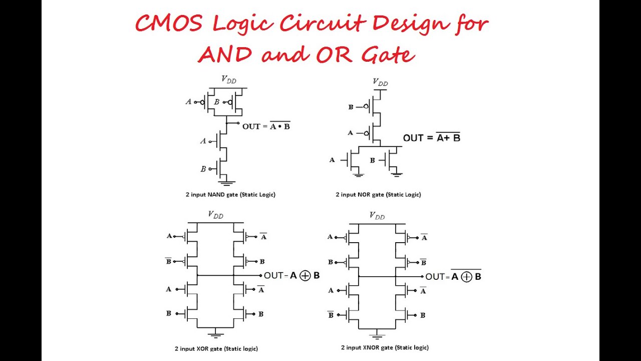
CMOS Logic Circuit Design for AND and OR Gate

Bidirectional Shift Register: Basics, Circuit, Designing, Block Diagram, Working, and Waveforms
5.0 / 5 (0 votes)