grid connected pv system | Step by step implementation of 3 MW Grid-connected Solar PV System
Summary
TLDRThis video tutorial offers a detailed guide on implementing a 3-megawatt grid-connected solar PV system. The presenter explains the setup, including PV array configuration, use of a boost converter with RLC series branch, and a double-stage conversion process. The video also covers the MPPT algorithm for maximum power extraction, inverter design using a universal bridge, and control logic for voltage and current. The simulation and testing of the system are demonstrated, showing how it handles varying irradiation levels and ensures efficient power transfer to the grid.
Takeaways
- 🌟 The video is a tutorial on implementing a 3-megawatt grid-connected solar PV system.
- 🔍 The presenter uses a specific solar PV model with 213.15 W panels and discusses their arrangement in series and parallel strings.
- 🔌 The system configuration involves 11 panels in series and 1300 parallel strings to achieve the maximum power point tracking.
- 🚀 The video demonstrates the use of a boost converter with a double-stage conversion process for efficient energy extraction.
- 🔄 The MBBT (Matlab-based Boost Converter Technique) algorithm is utilized for controlling the boost converter to extract the maximum power from the PV panels.
- 💡 The design includes components such as RLC series branches, inductors, IGBT switches, diodes, and output capacitors for the converter.
- 🔋 The video explains the process of designing the right capacitance and inductance values for the boost converter.
- ⚙️ A universal bridge inverter is used in the system, with details on its configuration and connection.
- 📊 The presenter discusses the importance of measuring PV data, including voltage, current, and power, and how to calculate them.
- 🔄 The control logic for the inverter includes voltage and current control, with a focus on maintaining a DC link voltage of around 600 volts.
- 🌡️ The system accounts for environmental factors such as irradiation and temperature, which are essential for the performance of the solar PV system.
Q & A
What is the purpose of the video?
-The purpose of the video is to provide a step-by-step guide on implementing a 3-megawatt grid-connected solar PV system.
What is the power rating of the solar PV model used in the video?
-The solar PV model used in the video has a power rating of 213.15 Watts.
How many panels are considered in series and parallel for the system?
-The system considers 11 panels in series and 1300 panels in parallel.
What is the maximum power point voltage of the system?
-The maximum power point voltage of the system is around 319 volts.
What is the maximum power output of the system?
-The maximum power output of the system is 3.04 megawatts.
What type of converter is used in the system for power optimization?
-A double-stage boost converter is used in the system for power optimization.
What is the role of the MPPT algorithm in the system?
-The MPPT (Maximum Power Point Tracking) algorithm is used to control the boost converter to extract the maximum power from the PV panels.
What is the switching frequency used for the inverter in the system?
-The switching frequency used for the inverter in the system is around 10 kHz (10 kilohertz).
How is the grid voltage and current measured in the system?
-The grid voltage and current are measured using a three-phase source with specific terminals configured for the measurement.
What is the role of the PLL (Phase-Locked Loop) in the system?
-The PLL is used to process the grid voltage and synchronize it with a 50 Hz frequency, which is essential for converting the grid current from ABC to DQ form.
How is the control logic for the inverter designed?
-The control logic for the inverter includes voltage control and current control using a PID controller, with the objective of maintaining a DC link voltage around 600 volts and providing a direct access current reference for control.
What is the significance of the scope measurements in the simulation?
-The scope measurements are significant for monitoring the DC link voltage, control voltage from the inverter control logic, and the output from the PWM (Pulse Width Modulation) generator, ensuring the system operates as expected.
How does changing the irradiation affect the system's performance?
-Changing the irradiation affects the system's performance by altering the power generated by the PV panels and consequently the power sent to the grid. For example, reducing the irradiation to 500 results in a power output closer to 1.5 megawatts.
Outlines

This section is available to paid users only. Please upgrade to access this part.
Upgrade NowMindmap

This section is available to paid users only. Please upgrade to access this part.
Upgrade NowKeywords

This section is available to paid users only. Please upgrade to access this part.
Upgrade NowHighlights

This section is available to paid users only. Please upgrade to access this part.
Upgrade NowTranscripts

This section is available to paid users only. Please upgrade to access this part.
Upgrade NowBrowse More Related Video

Sizing PV for applications without batteries
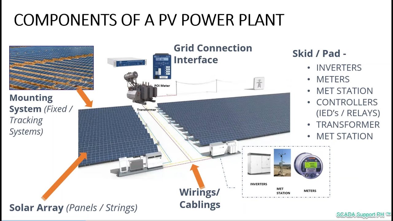
Solar Photovoltaic (PV) Power Plant

PV Grid | Harmonic Mitigation in Grid connected PV using Shunt Active Filter | Shunt Active Filter
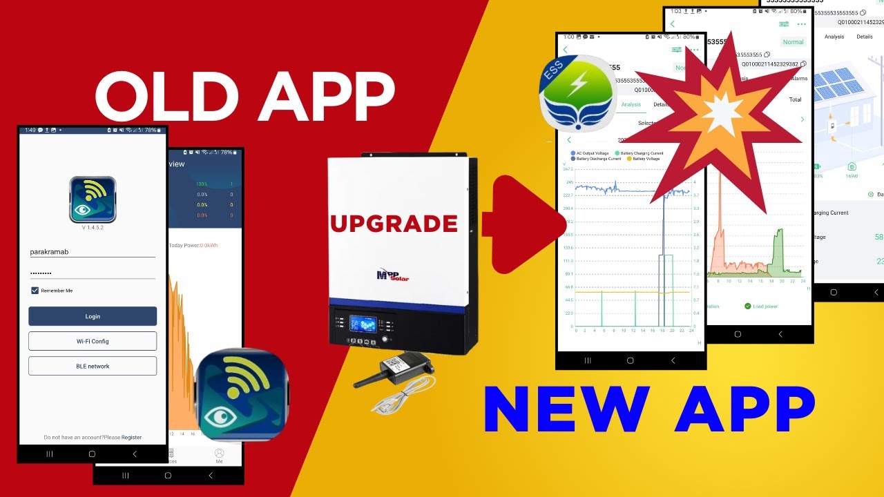
SmartESS App Changed Everything for My MPP Solar Inverter!

Solar power plant case study
Praktek Penyimpanan Arsip Sistem Subyek (Subyek Filling System )
5.0 / 5 (0 votes)