Form, Lift, Drag and Propulsion
Summary
TLDRThis script delves into the intricacies of fluid dynamics, focusing on flow separation from boundaries and its impact on various applications. It explains how adverse pressure gradients and shear zones in boundary layers lead to separation, affecting flow patterns, drag, and potentially causing structural issues. The video discusses methods to mitigate separation, such as streamlining and controlling boundary layers, and explores the concept of circulation and its role in cross-thrust and lift, particularly in the context of airfoils and propellers. It concludes with insights into the design of propulsive machinery, emphasizing the importance of blade shape and flow dynamics in efficiency.
Takeaways
- π« Separation of flow from a boundary is not just a geometric effect; it requires an adverse pressure gradient and a zone of flow as produced by shear in the boundary layer.
- π The central streamlines do not separate as pressure rises toward the point of stagnation, but separation occurs when the fluid in contact with a surface is at rest and cannot be further decelerated.
- π Separation points on bodies of appreciable curvature move forward from the zone of maximum pressure rise to where deceleration first occurs.
- π¨ Separation leads to changes in flow patterns, increased boundary drag, energy expenditure, and can cause flow oscillation, pressure fluctuations, noise, and structural damage.
- πͺ Parachutes and baffles operate on the principle of separation, but in general, separation should be avoided by controlling the boundary layer or the pressure gradient.
- π The retardation by shear can be offset by moving boundaries, preventing separation, similar to discharging fluid tangentially into the boundary layer region.
- π The drag coefficient indicates the effect of separation and is the ratio of the longitudinal force exerted by the flow to the stagnation pressure.
- π Streamlining can reduce drag significantly, especially under optimum conditions, by minimizing the separation surface and adverse pressure gradient.
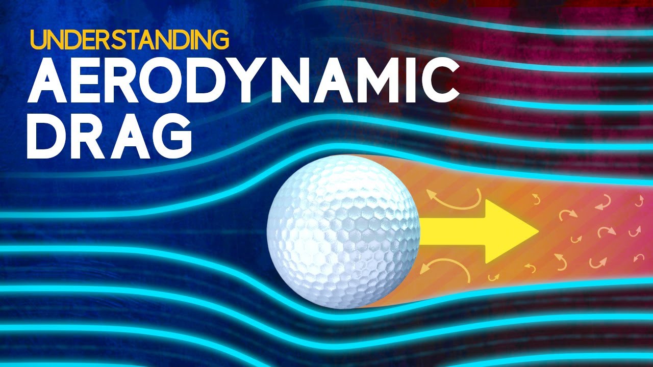
- β« A sphere represents intermediate streamlining, with a pressure distribution indicating separation still occurs, as shown by smoke injection into the wake.
- π The mathematical concept of circulation is useful in analyzing the cross-thrust exerted on bodies in relative motion, defined as the line integral of the tangential component of velocity around a closed curve.
- π« Lifting veins are designed to take advantage of flow-induced cross-thrust, with a lift coefficient proportional to the relative circulation and the angle of attack.
Q & A
What is the primary cause of flow separation in fluid dynamics as described in the script?
-Flow separation primarily occurs due to an adverse pressure gradient, which is common in regions of deceleration, and also requires a zone of already existing flow, such as that produced by shear in the boundary layer.
Why do central streamlines not separate as the pressure rises toward the point of stagnation?
-Central streamlines do not separate because the flow between them is not affected by shear, and the fluid in contact with a splitter plate is already at rest and cannot be further decelerated.
What are the three important occurrences that result from flow separation?
-The three important occurrences are changes in the anticipated flow pattern, the production of boundary drag which expends energy through the generation of eddies that rapidly transform into turbulence, and the potential for flow oscillation leading to pressure fluctuation, noise generation, and possibly structural damage.
How can separation be avoided in the operation of parachutes and baffles?
-Separation can be avoided by controlling the boundary layer or the pressure gradient, or both. For example, if the boundary moves with the flow, the retardation by shear is offset, preventing separation.
What is the purpose of guide vanes in fluid dynamics as mentioned in the script?
-Guide vanes are used to change the pressure field as a whole. They can conform to the original boundary and increase the relative radius of curvature locally, or they can be used to redesign the structure to improve flow efficiency.
What is the drag coefficient and how is it related to separation in fluid dynamics?
-The drag coefficient is a dimensionless number that indicates the effect of separation. It represents the longitudinal force exerted by the flow per unit projected area in its ratio to the stagnation pressure. It helps in understanding the resistance of a body moving through a fluid.
How does the shape of a body affect its drag in fluid dynamics?
-The shape of a body affects its drag by influencing the flow pattern around it. A streamlined shape reduces drag significantly by minimizing the pressure reduction at the rear and the adverse pressure gradient.
What is the significance of circulation in analyzing the cross-thrust exerted on certain bodies in relative motion?
-Circulation, defined as the line integral of the tangential component of velocity around a closed curve, is a measure of the fluid's tendency to circulate around the curve. It is crucial in analyzing cross-thrust because it affects the velocity and pressure distribution around bodies, leading to side forces.
How does the angle of attack of a lifting vein affect its lift coefficient?
-The lift coefficient of a lifting vein is proportional to the relative circulation, which in turn is proportional to the sine of the angle of attack. As the angle of attack increases, the lift increases until a point called stall is reached, after which the lift decreases.
What is the effect of aspect ratio on the lift-to-drag ratio of a lifting vein?
-The lift-to-drag ratio of a lifting vein decreases as the aspect ratio (length over chord) decreases. This is due to a tip effect, where flow occurs around the end of the vein, diminishing the pressure difference and thus reducing efficiency.
How does the design of a propeller blade vary with its radial position?
-Each radial section of a propeller blade moves with a different velocity, so the blade must vary continuously in shape from tip to hub. This variation ensures that each element of the blade has a different angle of attack to maintain efficient design.
Outlines
π Fluid Dynamics and Flow Separation
This paragraph delves into the complexities of fluid dynamics, particularly focusing on the phenomenon of flow separation from boundaries. It explains how separation occurs not only due to an adverse pressure gradient but also requires a zone of flow affected by shear in the boundary layer. The script discusses the effects of separation, such as altered flow patterns, increased boundary drag, and potential flow oscillations, which can lead to structural damage. It also highlights methods to control or prevent separation, such as manipulating the boundary layer or pressure gradient, and introduces the concept of guide veins to improve flow efficiency. The importance of understanding separation is emphasized through its relevance in various applications like parachutes and baffles, and the paragraph concludes with an explanation of the drag coefficient and its significance in assessing the impact of separation on pressure distribution and flow resistance.
π°οΈ Streamlining and the Impact of Shape on Fluid Resistance
The second paragraph examines the influence of an object's shape on the fluid resistance it encounters, illustrating how streamlined forms can significantly reduce drag. It discusses the concept of streamlining and how it can minimize the adverse pressure gradient and separation effects, leading to a reduction in boundary layer drag. The paragraph provides examples of how adding a rounded front or a well-faired tail piece can mitigate separation and reduce drag. It also touches on the relationship between a body's projected area, shape, and the resulting resistance, using the sphere as a reference point for comparison. The discussion extends to the effects of two-dimensional flow and the drag coefficient, explaining how it can be influenced by the body's shape and the presence of other bodies in the flow field. The paragraph concludes with an exploration of the mathematical concept of circulation and its role in analyzing cross-thrust on bodies in relative motion.
π Vorticity and the Dynamics of Lifting Veins
This paragraph explores the concept of vorticity and its effects on the dynamics of lifting veins. It explains how circulation, a measure of the fluid's tendency to circulate around a curve, can influence the flow pattern and pressure distribution around bodies like cylinders. The paragraph describes the cross-thrust phenomenon, which can cause deflection in spinning objects, and introduces the Karman vortex street, a series of vortices shed alternately from the sides of an oscillating cylinder. It also discusses the instability of certain structural sections, such as the Tacoma Narrows Bridge, and how circulation can be harnessed in lifting veins to generate lift. The paragraph concludes with an analysis of the lift coefficient in relation to the angle of attack and the effects of stall on the flow pattern around an airfoil.
βοΈ Aerodynamics of Propellers and Hydrofoils
The fourth paragraph focuses on the aerodynamics of propellers and hydrofoils, explaining how the principles of lifting veins are applied to these technologies. It discusses the importance of blade shape and angle of attack in determining the lift and drag forces that contribute to the axial thrust and torque of a propeller. The paragraph also touches on the effects of tip vortices and the downwash they create, which can impact the efficiency of lifting surfaces. It further explains how hydrofoils can be used to lift boats out of the water, reducing wave resistance and increasing speed and stability. The discussion extends to the historical use of lifting principles in windmill technology and the modern application of these principles in various types of propellers and turbines.
πͺοΈ Advanced Propulsion Systems and Fluid Dynamics
The final paragraph discusses advanced propulsion systems, such as jet engines and torque converters, and their underlying fluid dynamics principles. It explains how stationary guide vanes and moving blades work together to create thrust in a manner similar to lifting veins. The paragraph also addresses the challenges of designing for the compressibility of gases and the importance of matching flow rates, approach directions, and runner speeds to avoid stall and maintain efficiency. It concludes with a look ahead to the next film in the series, which will delve into the effects of compressibility on fluid dynamics.
Mindmap
Keywords
π‘Separation of Flow
π‘Boundary Layer
π‘Adverse Pressure Gradient
π‘Drag Coefficient
π‘Streamlining
π‘Circulation
π‘Lift
π‘Tip Vortex
π‘Aspect Ratio
π‘Cavitation
π‘Compressibility
Highlights
The concept of flow separation from a boundary and its effects on fluid dynamics.
Explanation of how separation reduces the curvature of the limiting streamline until a physically possible pressure field is realized.
The necessity of an adverse pressure gradient and a zone of already decelerated flow for separation to occur.
The behavior of central streamlines in relation to pressure changes and the role of shear in boundary layer separation.
The impact of separation on flow patterns, boundary drag, and the generation of turbulence.
How separation can cause flow oscillation, leading to pressure fluctuations, noise, and potential structural damage.
The importance of controlling boundary layer or pressure gradient to avoid separation in applications like parachutes and baffles.
Techniques to prevent separation, such as moving boundaries and fluid discharge into the boundary layer.
The use of guide veins to alter the pressure field and improve flow efficiency.
Introduction of the drag coefficient as a measure of separation effect and its significance in flow analysis.
The role of streamline form in reducing drag and the concept of streamlining in various applications.
The mathematical concept of circulation and its application in analyzing cross-thrust on bodies in relative motion.
Demonstration of how circulation can be produced by boundary layer shear around a rotating body.
The impact of oscillation of flow pattern on cross-thrust and the resulting oscillatory motion of structures.
The design principles of lifting veins to maximize flow-induced cross-thrust and their application in aircraft wings and hydrofoils.
The relationship between the lift coefficient, circulation theory, and the angle of attack of a lifting vein.
The effects of aspect ratio on the lift-to-drag ratio and the role of tip vortices in reducing efficiency.
The application of lifting vein principles in windmill and propeller design for efficient energy conversion.
The complexity of slipstream and tip vortex effects in ship propellers and their impact on thrust and torque.
The function of stationary guide veins in altering circulation without doing work, as seen in torque converters.
The general principle of using stationary and moving blades in jet engines for propulsive machinery.
Transcripts
[Music]
in our previous films separation of flow
from a boundary was treated as a purely
geometric effect a plate or orifice
diaphragm for example is usually too
thin for the flow to follow without an
impossibly low pressure at the
edge separation simply reduces the
curvature of the limiting stream line
till a physically possible pressure
field is
realized in general however separation
requires not only an adverse pressure
gradient as in any region of
deceleration but also a zone of already
flow as is produced by Shear in
the boundary
layer
here the central stream lines do not
separate as the pressure Rises toward
the point of stagnation because the flow
between them is not otherwise
but the fluid in contact with a
splitter plate is already at rest and
cannot be further decelerated so the
separation must take place if the flow
is to
continue as the boundary layer develops
around any body of appreciable curvature
the point of Separation rapidly moves
forward from the zone of maximum
pressure rise at the rear to the Zone
where deceleration first
occurs as a matter of fact no change in
boundary alignment is really
necessary just so long as there is a
sheer zone of low velocity and an
adverse pressure gradient such as
prevails beneath the front of this Ulus
surge moving slowly against the
flow
separation leads to three important
occurrences first the changes of the
anticipated flow pattern for instance
this channel expansion obviously does
not cause the flow itself to expand as
rapidly as
desired secondly it produces boundary
drags thereby expending energy through
the generation of edes which rapidly
transform to
turbulence finally it can lead to oscill
of the flow with a corresponding
pressure fluctuation boundary vibration
noise generation and perhaps even
structural
damage though separation is very
essential in the operation of parachutes
and baffles it should in general be
avoided by the control of the boundary
layer or the pressure gradient or of
both together if the boundary moves with
the flow for example the retardation by
Shear is offset and separation obviously
is
prevented much the same elimination of
separation is realized if as is now
beginning to occur fluid is discharged
tangentially into the boundary layer
region through boundary
slots even better results will next be
seen to obtain as the boundary layer
fluid is sucked into the slots as
rapidly as it is
a change in the pressure field
as a whole is provided by the
introduction of guide
veins these can be made to conform to
the original boundary and thus increase
the relative radius of curvature locally
or else the whole structure can be
redesigned accordingly as in the case of
this miter bend the flow is obviously
much worse without the veins but much
more efficient once veins have been
installed a type of Oiler number that
indicates the effect of separation is
known as the drag
coefficient the longitudinal force
exerted by the flow per unit projected
area in its ratio to the stagnation
pressure for extreme Degrees of
Separation as must occur at the edges of
this
dis measur of the pressure distribution
at the numbered Pomers on the front and
rear faces will show the cause of the
drag as air now begins to flow from left
to right the front of the dis becomes
subject to positive pressure and the
rear to appreciable
suction the integral of the pressure
distribution will yield the same Force
as that measured on such an air tunnel
Dynam
mometer the high drag of the yellow disc
can be reduced appreciably by adding a
rounded front which minimizes the
curvature of the separation surface and
thus somewhat alleviates the pressure
reduction at the
rear separation is almost completely
eliminated by adding a well fared tail
piece to reduce the adverse pressure
gradient since there can be no
resistance to steady irrotational flow
around the body with without separation
practically the only resistance now is
that of Shear within the boundary
layer under Optimum conditions the
process called streamlining can reduce
the drag some
95% since the resisting Force varies
with the projected area of a body as
well as with its shape at the same
velocity this streamline form would then
produce no more resistance than a dis of
less than a quarter its diameter
a sphere is intermediate between poor
streamlining and good
streamlining as can be seen from the
distribution of pressure measured at the
numbered
Pomers when flow takes place from left
to right the low pressure at the rear
compared with the high pressure at the
front indicates that separation still
occurs as is shown by injecting smoke
into the Wake the line of separation is
even ahead of the
midsection making the boundary layer
turbulent prematurely by a trip wire
tends to reduce the separation tendency
as is evident from the shift of the
separation point to the rear of the
midsection compared with a body
producing two-dimensional flow like this
long plate a more nearly axis symmetric
body Like A square has a much higher
wake pressure and hence a much lower
drag per unit
area the drag coefficient of a square
plate therefore is increased by cutting
it into more nearly two dimensional
strips and slightly separating
them a body that is in the wake of
another being in a zone of reduced
velocity experiences a great reduction
in drag as any cyle who has coasted
along behind a truck is well
aware these Elementary principles also
apply to more complicated structures
such as
buildings roofs should not be designed
for only positive loading since in high
winds they are more likely to be lifted
by suction due to separation than they
are to be blown
in chimneys obviously should not
terminate within zones of separation or
the smoke will fill the region behind
them this has se to be the case almost
regardless of the direction from which
the wind
comes probably the most UNAM line body
is a
parachute but obviously even this can be
designed for maneuverability
moreover even the human body in free
fall can control its turning moment
about three different
axes as this sky diver clearly
shows the mathematical concept of
circulation introduced in connection
with vorticity in our second film is
also useful in analyzing the cross
thrust that is exerted upon certain
bodies in relative
motion the circulation gamma is defined
as the line integral of the tangential
component of the Velocity completely
around a closed
curve it's thus a measure of the
tendency of the fluid to circulate
around the curve either in the One
Direction or in the
other the circular streamlines of an IR
rotational Vortex are all lines of of
constant circulation for the velocity
varies inversely and the circumference
directly with the
radius now if the velocity field of such
a Vortex is superposed upon the velocity
field of ir rotational flow around the
body say a circular
cylinder the velocity on the one side
will be augmented and on the other side
diminished in proportion to the relative
strength of the
circulation and the flow pattern will
change accordingly
where the velocity is increased the
pressure will be reduced and vice versa
so that a side thrust will be exerted
upon the
cylinder such circulation can be
produced in actuality by boundary layer
Shear around a rotating
body this is Illustrated quite
graphically by Rolling a light paper
cylinder down a miniature C
jump because of the rotation of the
cylinder as it leaves the jump the cross
thrust will cause it to deviate quite
markedly from its normal parabolic
trajectory the same effect causes the
deflection of a spinning baseball or a
spinning pingpong ball from its normal
course if a cylinder is not rotating
however oscillation of the float pattern
will cause the circulation to vary first
in One Direction action and thenone in
the other with the result that there is
a rapid oscillation in the cross
thrust this explains the tendency for
telephone wires to sing in a high wind
or it explains the whistling sound that
is given off by this Rod as it swung
rapidly through the
air observation of the flow pattern
behind such a cylinder will reveal the
alternate shedding of vortices either
side of the center line the circulation
around each Vortex being just the
opposite of the momentary circulation
around the cylinder producing the side
thrust the succession of such vortices
is called the Caron Vortex
Trail if the cylinder is free to
oscillate under the side thrust as it is
if suspended from light Springs it will
gradually develop an oscillatory Motion
in the transverse Direction and
eventually move back back and forth over
a distance about equal to its
diameter an elliptical cylinder with
major axis in the direction of the flow
will have a more limited amplitude of
oscillation whereas one with its major
axis normal to the flow will oscillate
much more
marketly some asymmetric forms like
either this semicircular cylinder or ice
encrusted telephone wires are unstable
in the T will tend to oscillate farther
and farther with eventual breakage of
the suspension as a
result a similar sort of instability is
found in various structural sections in
particular the Tacoma Narrows Bridge
here seen oscillating in a high wind
prior to Ultimate
failure
a body that is so designed is to take
maximum advantage of flow induced cross
thrust is known as a lifting vein the
circulation of the starting Vortex seen
here is matched by an equal and opposite
lift producing circulation around the
foil the fact that circulation actually
occurs around the foil is seen from the
vortices that detach as the foil is
stopped
a lift coefficient can be written for a
vein of length L and chord c as the
lifting Force per unit vein
area in its ratio to the stagnation
pressure according to the circulation
theory of lift this coefficient is
proportional to the relative
circulation which in turn is
proportional to the sign of the angle of
attack of the vein
a plot of the measured lift coefficient
against angle of attack shows good
agreement with the circulation Theory at
small angles but a great deviation at
high angles as the phenomenon known as
stall
occurs by means of smoke filaments the
gradual development of stall or Leading
Edge separation is readily seen from the
change in flow pattern around this
symmetrical vein as its angle of attack
is continuously
increased Pomers at the numbered points
around the profile of a vein show that
in a steady crossflow a circulation
induced with growing angle of attack
produces a pressure below and a suction
above the vein the difference increasing
as the angle of attack increases till
stall suddenly
occurs as seen from this polar diagram
of lift versus drag a well-designed
lifting vein will display an efficiency
or racial of lift to drag as high as 25
or
30 this is for an aspect ratio length
over cord that is very
great as the aspect ratio decreases
however the ratio of lift to drag
steadily
diminishes this is because of a tip
effect much like that of the shortened
plate in which flow occurs around the
end and diminishes the pressure
difference near the middle of a vein
smoke filaments show only a
two-dimensional separation
effect near the end however as the vein
is inclined first this way and then that
the pressure on one side and suction on
on the other give rise to an additional
circulation effect an intense tip
Vortex this end view of the same
foreshortened vein shows the growth of
the tip Vortex to
Perfection the resulting flow directly
behind the vein has a downward component
called downwash which necessarily
increases with decreasing aspect
ratio
lifting veins are used not only for the
wings of airplanes but also under modern
hydrofoil boots to lift the holes
completely out of the
water this is an experimental Grumman
craft being tested for the maritime
Administration elimination of wave
resistance obviously leads to much
greater speed and
stability the first use of the lifting
vein principle occurred many centuri
entries ago in connection with the
windmill forerunners of the more recent
airplane propeller shown
here since each radial section of a
propeller moves with a different
velocity for efficient design the blade
as a whole must vary continuously in
shape from tip to
HUB each successive element of the blade
has the same forward speed but a
tangential speed that is proportional to
the
radius hence each will have a different
angle of advance and this in turn makes
necessary a variable angle of the
blade for the single blade element now
shown the forward speed and the
tangential speed determine its direction
of motion relative to the
fluid this and the geometry of the
element then control the angle of attack
the lift and drag measured right
relative to the direction of
motion evidently both contribute to the
axial thrust of the propeller and to the
tangential force that is involved in the
torque a ship propeller usually has
Blades of large cord so that the load is
distributed over a greater
area thus the local pressure drop Will
normally not be great enough to produce
cavitation here however
tests conducted under extreme conditions
in a cavitation tunnel of the Navy's
David Taylor model Basin show by water
vapor formation the decrease in
slipstream diameter that must always
occur as the propeller accelerates the
passing
fluid when the same state of flow is
seen in slow motion the tip Vortex is
found to yield a spiral tube of water
vapor which shows the actual complexity
of the
slipstream
encasing a propeller in a duct as in a
pump or turbine eliminates both a tip
effect and the necking down of the
slipstream the pitch of the blades is
often variable from the breaking limit
to full feather in order to control the
efficiency and other operating
characteristics blowers pumps and turbin
Vary from the axial flow or propeller
type just shown to the radial flow or
centrifugal type of this Alice Charmers
turbine a radial flow unit is shown
schematically in the
laboratory the blue stationary guide
veins give the oncoming flow a
tangential component which ideally is
brought again to Zero by the time the
flow leaves the red veins of the moving
Runner
the work that is done by the fluid on
the runner is proportional to the change
in circulation that is
produced if the camera is now rotated at
the same speed as the runner to show the
flow relative to its
blades these are seen to act as lifting
veins much like those previously
discussed the components of both lift
and drag evidently control the tangent
force on the runner that does the useful
work however if the rate of flow
direction of approach and Runner speed
are not properly related an effect
comparable to stall will occur and the
efficiency will be
reduced a fluid coupling which serves as
a shock-free connection between driving
and driven Mach
Machinery consists of a pump the green
shaft and blades at the left and a
turban the blue shaft and blades at the
right compactly combined in a single
housing if the space is filled with a
fluid of appreciable density turning the
input shaft and Blades will cause the
output blades and shaft to yield the
same torque whether rotating or
stall because the circulation must
increase and decrease by the same amount
as the fluid passes from one side to the
other and Back
Again inclusion of a set of stationary
veins here shown in red permits the
circulation to be changed without doing
work so that the output veins will yield
a higher or lower
torque such a unit is called a torque
converter proper shape of the stationary
veins will even permit the output torque
to be reversed
inside the general principle of using
stationary guide veins visible in the
upper portion of this open model of an
aircraft jet
engine as well as moving blades is the
basis of most propulsive
Machinery though the elements are
carefully shaped and used in many
successive stages they are all basically
lifting veins here however not only the
density and viscosity of the gaseous
fluid must be considered but also its
compressibility a property of which the
effects will be treated in detail in the
next and last film of this
series
[Music]
oh a
5.0 / 5 (0 votes)