Experiment Direct current
Summary
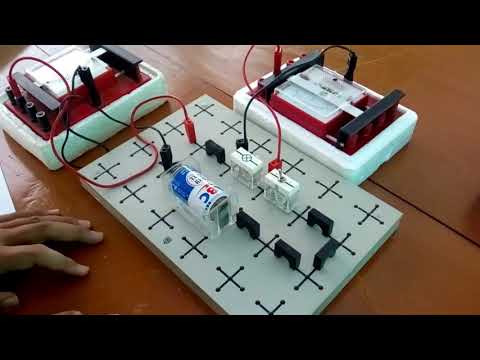
TLDRThe video demonstrates a hands-on experiment to measure voltage, current, and resistance in a simple electrical circuit using a digital multimeter (DMM). It guides viewers through identifying resistor values via color codes, connecting resistors in series and parallel, and systematically measuring total and individual resistances. The script also explains proper probe placement for accurate voltage and current readings across each resistor and the overall circuit. Measurements are repeated for precision, and results are organized in tables. The tutorial emphasizes understanding breadboard connections and safe, accurate usage of measurement tools, providing a comprehensive, practical introduction to basic electrical experimentation.
Takeaways
- 😀 Start by placing the DMM probe at the battery terminals: black probe on the negative terminal, red probe on the positive terminal.
- 😀 Gradually reduce the range on the DMM until the desired data (voltage) is displayed and record it with the associated uncertainty.
- 😀 Understand resistor color codes: The first band represents 'brown' (digit 1), the second band 'black' (digit 0), and the third band 'red' (two zeros), indicating a resistance of 1000 ohms.
- 😀 Set the DMM to the resistance range and measure the resistance across the resistor's terminals.
- 😀 Record all measured resistance values and note that the common connection across the breadboard ensures vertical holes are connected but there's no connection through the middle divider.
- 😀 Connect resistors 1 and 2 in series, then measure and record the total resistance. Repeat for resistors 3 and 4 in a similar setup.
- 😀 For resistors 1 and 2 connected in series, label it as R12, and for resistors 3 and 4 connected in series, label it as R34.
- 😀 When R12 is placed in parallel with R34, measure the equivalent resistance (R1234) and record it, repeating the measurement three times.
- 😀 Measure and record the voltage across each resistor in the circuit, starting with R1 and following the setup instructions for other resistors (like R2).
- 😀 For current measurements, disconnect the right leg of R1, connect probes between the right leg of R1 and the left leg of R2, and record the current as I_R1. Repeat the current measurement for other components in the circuit and tabulate all values.
Q & A
How should the DMM probes be connected to measure the battery voltage?
-The black probe should be placed at the negative terminal and the red probe at the positive terminal. Adjust the DMM range until a stable voltage reading is displayed.
What is the significance of resistor color bands?
-Color bands indicate the resistance value of a resistor. The first two bands represent digits, the third band is a multiplier, and the fourth band (if present) indicates tolerance.
How is a 1000 Ω resistor identified using color codes?
-The first band is brown (1), the second band is black (0), and the third band is red (×100), giving a resistance of 1000 Ω.
How should resistors be measured using a DMM?
-Set the DMM to resistance mode, place the probes on the resistor terminals, and record the resistance value.
What is the method to connect resistors in series on a breadboard?
-Connect the end of one resistor to the start of the next resistor. For example, R1 connects to R2 to form R12. Measure the total resistance across the series combination.
How is the equivalent resistance calculated when resistors are connected in parallel?
-For resistors R12 and R34 in parallel, the equivalent resistance R1234 is calculated using: R1234 = (R12 × R34) / (R12 + R34).
Where should DMM probes be placed to measure voltage across a resistor?
-Probes should be placed in parallel across the resistor's terminals to measure the voltage drop accurately.
How is current measured through a resistor using a DMM?
-Disconnect one end of the resistor and connect the DMM in series between the disconnected end and the circuit to measure the current passing through.
Why is it recommended to repeat measurements multiple times?
-Repeating measurements increases accuracy and helps identify any inconsistencies or errors in the readings.
What is the common connection rule in a breadboard?
-Vertical holes in a column are electrically connected, while horizontal rows across the middle divider are not connected.
How can one measure the total current in a circuit with multiple resistors?
-Insert the DMM in series with the entire circuit path before or after the resistor network to measure total current.
What precautions should be taken when measuring voltage and current?
-Ensure proper probe placement and polarity, select appropriate DMM range, and avoid short circuits. Voltage is measured in parallel and current in series.
Outlines

This section is available to paid users only. Please upgrade to access this part.
Upgrade NowMindmap

This section is available to paid users only. Please upgrade to access this part.
Upgrade NowKeywords

This section is available to paid users only. Please upgrade to access this part.
Upgrade NowHighlights

This section is available to paid users only. Please upgrade to access this part.
Upgrade NowTranscripts

This section is available to paid users only. Please upgrade to access this part.
Upgrade Now


5.0 / 5 (0 votes)