Understanding Sensor Fusion and Tracking, Part 2: Fusing a Mag, Accel, & Gyro Estimate
Summary
TLDRIn this video, Brian from MATLAB Tech Talk explains how sensor fusion can be used to estimate an object's orientation, also known as attitude or heading. He covers the use of magnetometers, accelerometers, and gyros, focusing on their roles and the challenges involved. The video discusses common issues like accelerometer linear accelerations and magnetometer disturbances, and introduces fusion algorithms like the complementary and Kalman filters to improve accuracy. Practical demonstrations using an Arduino and MATLAB are provided to illustrate these concepts in action.
Takeaways
- 📐 Sensor fusion is used to estimate an object's orientation by combining data from multiple sensors.
- 🌐 Orientation can also be referred to as attitude or heading, depending on the context.
- 📱 Common sensors for orientation estimation in phones and autonomous systems include a magnetometer, accelerometer, and gyro.
- 🛩️ Examples of orientation estimation include satellites using star trackers and airplanes using angle of attack sensors.
- 🔄 Orientation can be represented using roll, pitch, and yaw, or more complex methods like Direction Cosine Matrix (DCM) and quaternions.
- 📏 The goal is to determine the rotation between an object's coordinate frame and an external reference frame.
- 🔧 For a phone on a table, orientation can be estimated using a magnetometer and accelerometer, with cross-products used to calculate north, east, and down vectors.
- 🧲 Magnetometers can be affected by magnetic disturbances, which can be calibrated out if they rotate with the magnetometer.
- 📊 Linear accelerations and rotations can corrupt accelerometer data, which can be mitigated by predicting and removing linear acceleration or using a gyro.
- 🤖 Combining sensor data using algorithms like complementary filter or Kalman filter can provide more accurate orientation estimates by balancing the strengths and weaknesses of each sensor.
Q & A
What is sensor fusion and how is it used to estimate an object's orientation?
-Sensor fusion is the process of combining data from multiple sensors to estimate an object's orientation, also known as attitude or heading. It uses various sensors like magnetometers, accelerometers, and gyros to determine how an object is facing relative to a reference frame.
What are some alternative names for orientation in different contexts?
-In different contexts, orientation can be referred to as attitude or heading. Heading specifically refers to the direction along a 2D plane.
What is an attitude and heading reference system (AHRS)?
-An Attitude and Heading Reference System (AHRS) is a system that uses sensor fusion algorithms to determine an object's orientation or attitude relative to an inertial reference frame, which is often the stars for satellites or the local horizon for aircraft.
What are the three main sensors typically used in a sensor fusion system for orientation estimation?
-The three main sensors typically used in a sensor fusion system for orientation estimation are a magnetometer, an accelerometer, and a gyroscope.
How can a magnetometer and accelerometer be used to determine the absolute orientation of a stationary phone on a table?
-A magnetometer and accelerometer can determine the absolute orientation of a stationary phone by measuring the direction of gravity and the magnetic field in the body frame. The cross-products of these vectors with the 'down' vector (opposite to gravity) can be used to find the 'north', 'east', and 'up' directions, forming the basis for the orientation.
What is the issue with using a magnetometer for orientation estimation when the system is in motion?
-When the system is in motion, the magnetometer not only measures the Earth's magnetic field but also any disturbances caused by the motion, which can corrupt the estimate of the orientation.
What are hard iron and soft iron sources in the context of magnetometer calibration?
-Hard iron sources are objects that generate their own magnetic fields, like magnets in an electric motor or coils with current. Soft iron sources are magnetic materials that distort the magnetic field as it passes through them. Both types can affect the magnetometer readings and need to be calibrated out.
How can linear accelerations affect the accuracy of an accelerometer's measurement of gravity?
-Linear accelerations can affect the accuracy of an accelerometer's measurement of gravity because the accelerometer measures all linear accelerations, not just gravity. If the system is moving or accelerating, the accelerometer will sense this acceleration in addition to gravity, which can throw off the estimate of 'down'.
What is the concept of dead reckoning in the context of gyroscope-based orientation estimation?
-Dead reckoning is the process of estimating the orientation of an object by integrating the angular rate measurements from a gyroscope over time. It assumes that the initial orientation is known and updates the orientation based on the change in angle due to the angular rate.
How does sensor fusion help to address the limitations of using a gyroscope alone for orientation estimation?
-Sensor fusion helps to address the limitations of using a gyroscope alone by combining the gyroscope's measurements with those from other sensors like the magnetometer and accelerometer. This combination can correct for the drift that occurs in the gyroscope's estimation due to sensor bias and noise, providing a more accurate and stable orientation estimate.
What are some common sensor fusion algorithms mentioned in the script?
-Some common sensor fusion algorithms mentioned in the script include the complementary filter, the common filter, and the more specialized Mahony filter.
How does the complementary filter work in blending the estimates from the magnetometer-accelerometer and the gyroscope?
-The complementary filter works by placing a 'slider' at a position on a scale that represents trust in each solution. The designer manually decides the position of the slider, which determines the weighting of the magnetometer-accelerometer solution versus the gyroscope's dead reckoning solution. This blending emphasizes the strengths of each while minimizing their weaknesses.
What is the purpose of the common filter in sensor fusion?
-The common filter, also known as the Kalman filter, automatically calculates the optimal gain or position of the trust slider based on the noise levels in the measurements and the accuracy of the system model. It performs a kind of weighted averaging between the two solutions to provide a more accurate orientation estimate.
How does the integration of gyroscope measurements lead to drift in orientation estimation over time?
-The integration of gyroscope measurements, which acts like a low-pass filter, smooths out high-frequency noise but also accumulates errors over time due to sensor bias and random walk. This results in a gradual drift of the estimated orientation away from the true value.
Outlines

This section is available to paid users only. Please upgrade to access this part.
Upgrade NowMindmap

This section is available to paid users only. Please upgrade to access this part.
Upgrade NowKeywords

This section is available to paid users only. Please upgrade to access this part.
Upgrade NowHighlights

This section is available to paid users only. Please upgrade to access this part.
Upgrade NowTranscripts

This section is available to paid users only. Please upgrade to access this part.
Upgrade NowBrowse More Related Video

Understanding Sensor Fusion and Tracking, Part 3: Fusing a GPS and IMU to Estimate Pose

Noise Filtering in PID Control | Understanding PID Control, Part 3
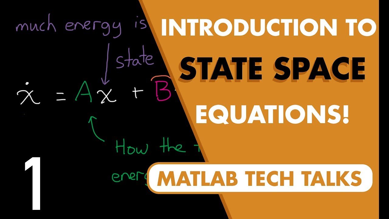
Introduction to State-Space Equations | State Space, Part 1

Extended Kalman Filter - Sensor Fusion #3 - Phil's Lab #37
Gyroscopic Instruments

Gyroscopic System - Flight Instruments
5.0 / 5 (0 votes)