Electrical Engineering: Ch 6: Capacitors (1 of 26) Basics (What is a Capacitor?)
Summary
TLDRThis video introduces the fundamental concepts of capacitors in electrical circuits. It explains that a capacitor consists of two metal plates separated by a small distance, often with a dielectric or air in between, and demonstrates how applying a voltage causes positive and negative charges to accumulate on opposite plates. The video details the concept of capacitance as the ratio of charge to voltage, provides the formula based on physical dimensions, and discusses the electric field between the plates. Practical capacitor units such as microfarads, nanofarads, and picofarads are highlighted, offering a clear understanding of how capacitors store and manage electric charge.
Takeaways
- 😀 A capacitor consists of two metal plates with a small distance between them, often with a dielectric material or air in between.
- 😀 When a voltage is applied to the plates, positive charge is driven onto one plate, causing an equal and opposite negative charge to appear on the other plate.
- 😀 The amount of charge that accumulates on the plates is related to the voltage applied, and the ratio of charge to voltage defines the capacitance of the capacitor.
- 😀 Capacitance can also be calculated using the physical dimensions of the capacitor: the plate area, distance between plates, and the dielectric constant (epsilon naught).
- 😀 The capacitance formula is: C = (epsilon naught * A) / D, where A is the plate area, D is the distance between plates, and epsilon naught is the permittivity of free space.
- 😀 The unit of capacitance is the Farad (F), where 1 Farad is equivalent to 1 Coulomb per 1 Volt.
- 😀 Capacitors are typically measured in smaller units like microfarads (μF), nanofarads (nF), and picofarads (pF) for most practical applications.
- 😀 The electric field between the plates is created due to the positive and negative charges on opposite plates, with the direction of the electric field pointing from the positive to the negative plate.
- 😀 The electric field's magnitude can be defined as the charge density divided by epsilon naught.
- 😀 The potential difference (voltage) between the plates is directly related to the electric field strength and the distance between the plates, expressed as V = E * D.
- 😀 Capacitance can be defined in terms of the ratio of charge (Q) to voltage (V), and it can also be related to physical dimensions using the formula: C = (epsilon naught * A) / D.
Q & A
What is a capacitor in simple terms?
-A capacitor is two metal plates placed side by side with a small distance between them, often separated by a dielectric material or air, which can store electrical charge when connected to a voltage source.
How does a capacitor get charged when connected to a battery?
-When a voltage is applied, positive charge accumulates on one plate and negative charge accumulates on the other. The positive charges on one plate repel positive charges on the opposite plate, creating an equal and opposite charge distribution.
What is the convention for the charges on a capacitor's plates?
-The convention is to consider the plate connected to the positive side of the battery as positively charged, and the plate connected to the negative side as negatively charged.
How is capacitance defined in terms of charge and voltage?
-Capacitance is the ratio of the amount of charge stored on the plates to the voltage applied across the plates, expressed as C = Q / V.
How can the physical dimensions of a capacitor determine its capacitance?
-The capacitance can be calculated using the formula C = ε₀ × A / d, where ε₀ is the permittivity of free space, A is the area of the plates, and d is the distance between them. Larger plate area increases capacitance, while larger distance decreases it.
What is the unit of capacitance and typical values used in circuits?
-The unit of capacitance is the Farad (F), defined as one Coulomb per one Volt. Typical circuit capacitors are much smaller, usually measured in microfarads (μF), nanofarads (nF), or picofarads (pF).
How is the electric field between capacitor plates defined?
-The electric field between the plates is defined as the charge density divided by ε₀, or E = Q / (ε₀ × A), where Q is the charge on the plate and A is the area of the plate.
What is the relationship between voltage, electric field, and distance between plates?
-The voltage between plates is the product of the electric field strength and the distance between the plates, V = E × d.
How does a smaller distance between capacitor plates affect capacitance?
-A smaller distance increases the interaction between positive and negative charges, strengthening the electric field and thereby increasing the capacitance.
Why do practical capacitors have much smaller capacitance than one Farad?
-Because storing one Coulomb of charge at one Volt requires a very large physical size, practical capacitors in circuits use microfarads, nanofarads, or picofarads, which are easier to manufacture and sufficient for most electronic applications.
How can capacitance be expressed using both charge-voltage ratio and physical dimensions?
-Capacitance can be expressed as C = Q / V (charge-voltage ratio) or C = ε₀ × A / d (using the physical dimensions of the plates and distance between them), showing two complementary ways to understand it.
Outlines

This section is available to paid users only. Please upgrade to access this part.
Upgrade NowMindmap

This section is available to paid users only. Please upgrade to access this part.
Upgrade NowKeywords

This section is available to paid users only. Please upgrade to access this part.
Upgrade NowHighlights

This section is available to paid users only. Please upgrade to access this part.
Upgrade NowTranscripts

This section is available to paid users only. Please upgrade to access this part.
Upgrade NowBrowse More Related Video
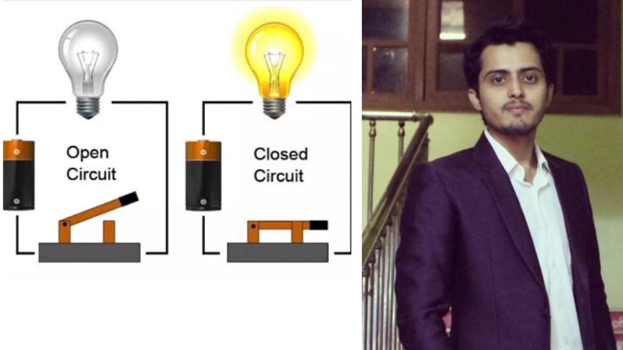
Open circuit | closed circuit | Short circuit | Easiest way to understand

Spenning, strøm og resistans - enkelt forklart

Power factor explained | Active Reactive Apparent Power correction

El condensador

The Basics of Electrical Components || Program Studi Teknik Elektro - MK : Bahasa Inggris

Análise de Circuitos - Aula 01
5.0 / 5 (0 votes)