SA18: Moment Influence Line
Summary
TLDRThis video provides a comprehensive explanation of moment influence lines for statically determinate beams, specifically focusing on determining vehicle locations that result in maximum bending moments at various points of a bridge or beam. It demonstrates how to construct and interpret moment influence lines, using examples such as points G, B, C, D, and E. The video also covers the theoretical process of drawing these lines by applying a positive bending moment and observing the resulting displacement of the beam. Finally, the video illustrates how to use influence lines for calculating maximum positive and negative bending moments under a moving load.
Takeaways
- 😀 Moment influence lines are used to determine the critical vehicle locations that result in maximum bending moments in beams under moving loads.
- 😀 The bending moment at mid-span (point G) of a beam is often the critical location for maximum bending moment.
- 😀 The moment influence line visually shows how the bending moment at a specific point varies as a unit load moves across the beam.
- 😀 For point G, the moment is zero when the unit load is at points A, C, D, and F, and it reaches its maximum positive value when the load is at point G.
- 😀 The moment at G becomes maximally negative when the unit load is at points B and E, as shown by the influence line.
- 😀 A moment influence line can be drawn qualitatively by placing a hinge at the point of interest, applying a positive bending moment, and observing the resulting displacement of the beam.
- 😀 When drawing a moment influence line, the beam segments are assumed to move vertically and rotate but not bend.
- 😀 The moment influence line for point B shows a negative moment when the unit load is to the right of point B, reaching its maximum when the load is at point C.
- 😀 For a hinge at point C, the moment influence line is a flat line, since the bending moment at a hinge is always zero regardless of load position.
- 😀 The moment influence line for point D involves analyzing the beam's displacement when a positive moment is applied at D, and it shows how bars AC and CD interact under the applied moment.
- 😀 To calculate the actual bending moment values, further analysis is required once the influence line has been drawn. This helps determine the maximum positive and negative moments for a specific point on the beam.
Q & A
What is a moment influence line?
-A moment influence line is a graphical representation that shows the bending moment at a specific point on a beam as a unit load moves across it. It helps in determining the critical vehicle locations that cause maximum or minimum bending moments in beams.
Why is the critical location in a beam typically mid-span?
-The mid-span of a beam is generally where the bending moment reaches its maximum, as the load distribution tends to create the largest moment at the center of the beam.
How does the vehicle location affect the bending moment at point G?
-The bending moment at point G changes as the vehicle moves across the bridge. The maximum positive moment occurs when the vehicle is at point G, and the maximum negative moments happen when the vehicle is located at points B and E.
What does the moment influence line for point G indicate?
-The moment influence line for point G shows how the bending moment at G varies as a unit load moves across the beam. It also indicates that the moment at G is zero at points A, C, D, and F, and reaches its maximum positive value when the unit load is at G.
How can the moment influence line be drawn qualitatively?
-To draw the moment influence line qualitatively, follow these steps: 1) Place a hinge at the point of interest. 2) Apply a positive bending moment to the hinge. 3) Draw the resulting displaced shape of the beam.
What role do hinges play in drawing moment influence lines?
-Hinges are used to conceptually isolate sections of the beam. By applying a positive bending moment at the hinge, it allows for the visualization of how the beam would displace and the resulting moment influence line.
Why is the moment influence line for point C flat?
-The moment influence line for point C is flat because a hinge at point C results in zero bending moment, regardless of where the unit load is located along the beam. Bending moment at a hinge is always zero.
What is the moment influence line for point D in the beam?
-The moment influence line for point D is determined by placing a fictitious hinge at D, applying a positive moment, and drawing the resulting displaced shape of the beam. This line indicates the critical locations for maximum or minimum bending moments at point D.
What is the significance of calculating maximum negative bending moments using the moment influence line?
-The moment influence line helps in identifying the location of the unit load that produces the maximum negative bending moment at a given point in the beam. This is useful for determining the worst-case scenarios for bending stress in the beam.
How can the maximum negative moment at point G be calculated using the moment influence line?
-To calculate the maximum negative moment at point G, the vehicle is placed at the critical location indicated by the moment influence line (in this case, at point F). The beam is then analyzed, and support reactions are calculated to determine the magnitude of the moment.
Outlines

This section is available to paid users only. Please upgrade to access this part.
Upgrade NowMindmap

This section is available to paid users only. Please upgrade to access this part.
Upgrade NowKeywords

This section is available to paid users only. Please upgrade to access this part.
Upgrade NowHighlights

This section is available to paid users only. Please upgrade to access this part.
Upgrade NowTranscripts

This section is available to paid users only. Please upgrade to access this part.
Upgrade NowBrowse More Related Video
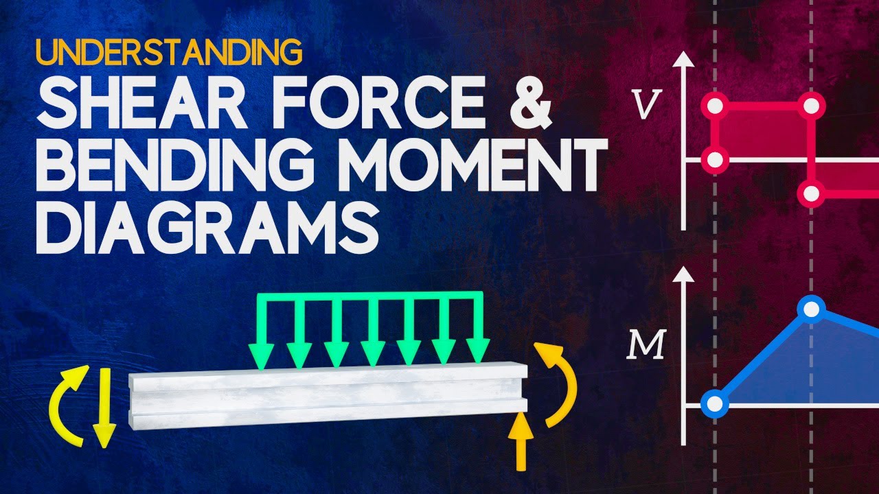
Understanding Shear Force and Bending Moment Diagrams

Structural Theory 1 Chapter 1 Structural Elements & Types of Structure Part 1 (with Subtitles)

S-10 Pengenalan Truss

BENDING MOMENT LAB
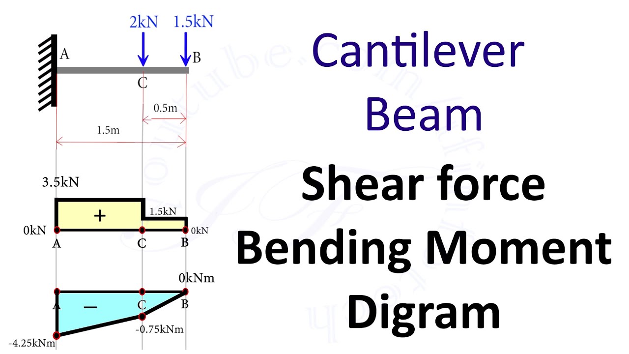
Cantilever Beam: Shear Force and Bending Moment Diagram [SFD BMD Problem 2] By Shubham Kola
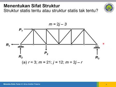
Mekanika Statis Tentu: Struktur Statis Tentu atau Struktur Statis Tak Tentu?
5.0 / 5 (0 votes)