Contoh Soal Teorema Thevenin dan Norton
Summary
TLDRIn this tutorial, Niftah Rahmadeni Putri from Muhammadiyah University of Riau explains how to solve problems using Thévenin’s and Norton’s theorems in electrical circuits. She walks through a detailed example, demonstrating how to calculate Thévenin voltage (VTH), resistance (RTH), and the current through a resistor. The tutorial also covers the conversion from Thévenin to Norton equivalent circuits, showing how the Norton current and resistance are determined. This step-by-step explanation is aimed at helping students grasp these key concepts in analog electronics, with practical applications for solving circuit problems.
Takeaways
- 😀 Tefvenin's theorem simplifies any linear electrical network into a single voltage source and resistance between two points (A and B).
- 😀 The voltage across two points A and B in an open circuit is known as the Tefvenin voltage (VTH).
- 😀 The first step in applying Tefvenin's theorem involves removing the load resistor and calculating the Tefvenin voltage by analyzing the remaining circuit.
- 😀 In this example, the voltage contributions from two voltage sources (10V and 20V) are calculated using voltage divider rules.
- 😀 After calculating the Tefvenin voltage (VTH), the next step is to find the Tefvenin resistance (RTH) by deactivating all voltage sources and calculating the equivalent resistance of the remaining circuit.
- 😀 Once VTH and RTH are known, the current through the load resistor (RL) is found using Ohm's law.
- 😀 The conversion from Tefvenin to Norton involves calculating the Norton current (IN) and Norton resistance (RN).
- 😀 The Norton current (IN) is found by dividing the Tefvenin voltage (VTH) by the Tefvenin resistance (RTH).
- 😀 The Norton equivalent resistance (RN) is the same as the Tefvenin resistance (RTH).
- 😀 Using the Norton equivalent circuit, the current through the load resistor (RL) is calculated using the current divider rule.
- 😀 The final result, 0.286 amps, is obtained by both Tefvenin and Norton methods, showing consistency in the calculations.
Q & A
What is the purpose of the video?
-The video explains how to solve problems related to Thevenin's and Norton's theorems in electrical circuits, as taught in the analog electronics course.
What is Thevenin's theorem?
-Thevenin's theorem states that any linear electrical network consisting of voltage sources and resistances can be simplified into an equivalent circuit with one voltage source (Vth) and one resistance (Rth) between two points A and B.
What are the steps involved in applying Thevenin's theorem to a circuit?
-The steps include: 1) Removing the load resistor, 2) Calculating the Thevenin voltage (Vth) by deactivating sources and applying voltage divider or node voltage analysis, 3) Finding the Thevenin resistance (Rth) by deactivating all voltage sources, and 4) Using Ohm's law to calculate the current through the load resistor.
How is the Thevenin voltage (Vth) calculated in the example?
-The Thevenin voltage (Vth) is calculated by considering the contributions of individual voltage sources, using voltage divider rules after deactivating other sources. The results from the two sources (10V and 20V) are added together to get Vth = 13.34V.
How is the Thevenin resistance (Rth) determined?
-Thevenin resistance (Rth) is determined by deactivating all voltage sources and calculating the equivalent resistance of the remaining resistive components. In this case, the two resistors (10 ohms and 20 ohms) are in parallel, resulting in Rth = 6.67 ohms.
How do you find the current through the load resistor using Thevenin's theorem?
-Using Ohm's law, the current is calculated by dividing the Thevenin voltage (Vth) by the sum of the Thevenin resistance (Rth) and the load resistor (Rl). The formula is: I = Vth / (Rth + Rl). In this case, the current is 0.286 amps.
What is the process for converting Thevenin's equivalent circuit to Norton’s equivalent circuit?
-To convert from Thevenin’s to Norton’s equivalent, the Thevenin voltage (Vth) is divided by the Thevenin resistance (Rth) to calculate the Norton current (In). In this case, In = Vth / Rth = 2 amps. The Norton resistance (Rn) is the same as the Thevenin resistance, which is 6.67 ohms.
What is the current divider law used for in the example?
-The current divider law is used to calculate the current flowing through the load resistor (Rl) when using Norton’s equivalent circuit. The formula is: I_Rl = In * (Rn / (Rn + Rl)), where In is the Norton current, Rn is the Norton resistance, and Rl is the load resistance.
What is the final current flowing through the 40 ohm resistor?
-The final current flowing through the 40 ohm resistor, calculated from both the Thevenin and Norton equivalent circuits, is 0.286 amps.
Why is it important to understand both Thevenin’s and Norton’s theorems?
-Understanding both Thevenin’s and Norton’s theorems is important because they provide different ways of simplifying complex electrical circuits, making it easier to calculate voltages, currents, and resistances in various parts of the circuit. Thevenin’s theorem simplifies to a voltage source and a resistance, while Norton’s simplifies to a current source and a parallel resistance.
Outlines

This section is available to paid users only. Please upgrade to access this part.
Upgrade NowMindmap

This section is available to paid users only. Please upgrade to access this part.
Upgrade NowKeywords

This section is available to paid users only. Please upgrade to access this part.
Upgrade NowHighlights

This section is available to paid users only. Please upgrade to access this part.
Upgrade NowTranscripts

This section is available to paid users only. Please upgrade to access this part.
Upgrade NowBrowse More Related Video

Hambatan Pengganti Rangkaian Seri, Paralel Dan Campuran

Hukum Ohm

[NEW VERSION!] RANGKAIAN PARALEL DAN SERI PARALEL | Rangkaian Listik Arus Searah - Fisika Kelas 12

Geradores, receptores e resistores - Eletrodinâmica - Aula 16 - Prof. Marcelo Boaro
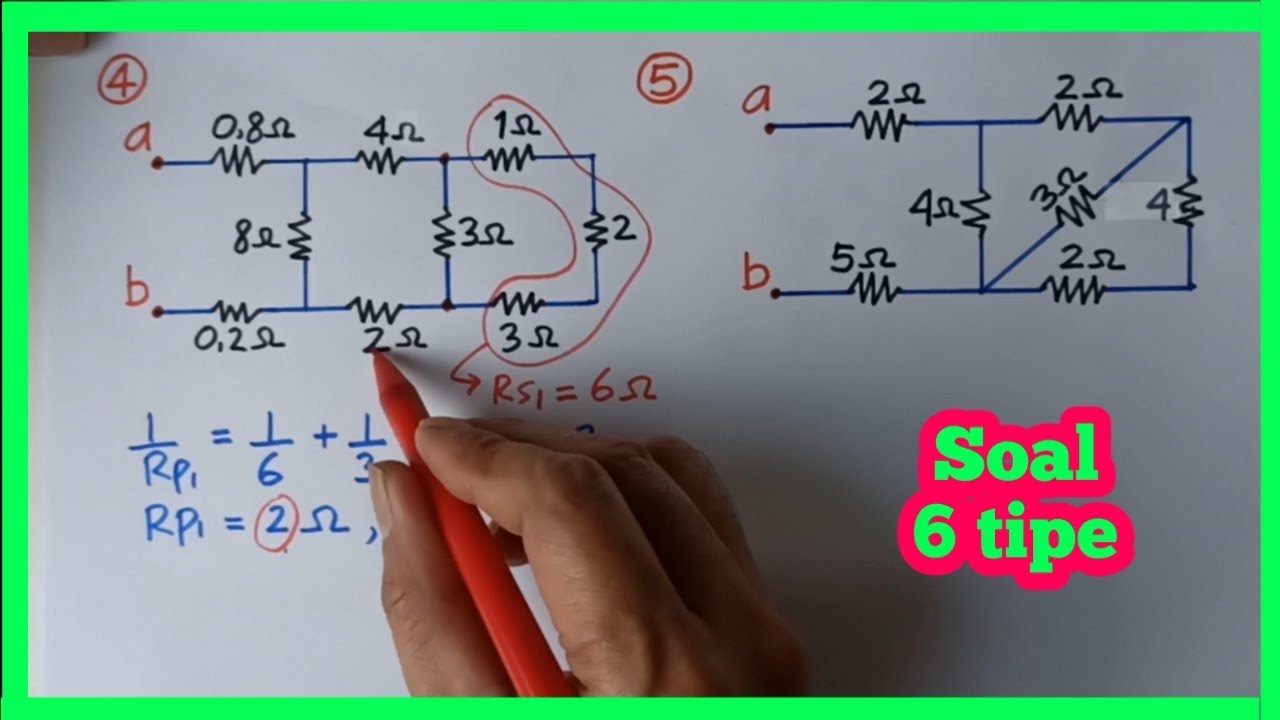
Menghitung Hambatan total / pengganti rangkaian listrik seri paralel majemuk
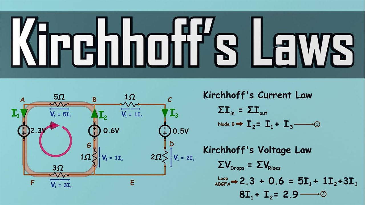
Kirchhoff's Laws - How to Solve a KCL & KVL Problem - Circuit Analysis
5.0 / 5 (0 votes)