Cara Desain Dinamo - (Motor Induksi 3 Fasa)
Summary
TLDRIn this video, the process of designing a three-phase induction motor is explored, drawing parallels with transformer design. Key steps include determining motor specifications, calculating synchronous rotation, choosing wire diameter, determining groove size, and calculating the number of groups for the windings. The speaker demonstrates calculations for current, wire diameter, and flux area, providing a detailed explanation of winding configurations and angles. The final result is a complete motor design, with technical details ensuring efficiency and functionality in creating a 1000W, 50Hz motor with specific voltage and pole requirements.
Takeaways
- 😀 The design process for a three-phase induction motor shares similarities with designing a transformer, with key steps involving subject determination, wire diameter selection, groove determination, and number of groups calculation.
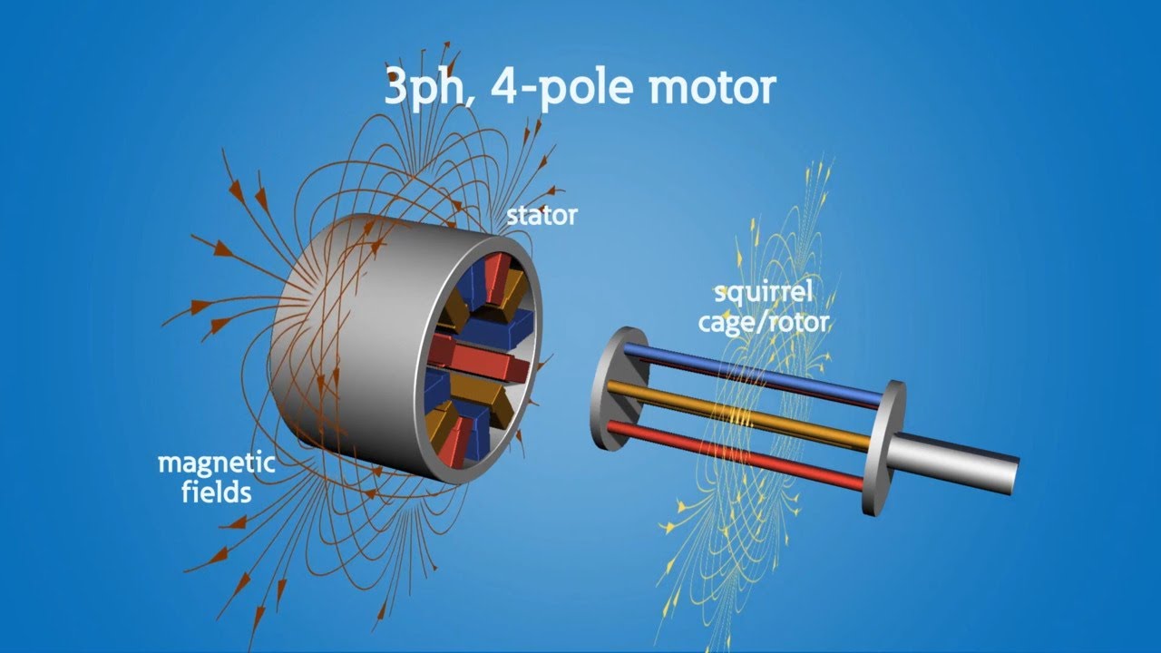
- 😀 The motor specifications being designed include a 1000 W power, 50 Hz frequency, 380 V voltage source, 0.70 efficiency, and 0.8 power factor, with 4 poles in a star connection.
- 😀 Synchronous speed is calculated based on the number of poles, which results in 1500 RPM for this motor.
- 😀 To determine the wire diameter, the phase voltage is first calculated using a star connection, which leads to a phase voltage of 219.4 V.
- 😀 The current is calculated using the formula: power / (√3 * voltage * efficiency * power factor), resulting in a current of 2.7 A.
- 😀 The wire cross-sectional area is found by dividing the current by 5 A/mm², which gives 0.54 mm², leading to a wire diameter of 0.803 mm using the circle formula.
- 😀 The motor groove dimensions are specified as an outer diameter of 180 mm, an inner diameter of 100 mm, and a thickness of 120 mm, with 36 slots.
- 😀 The design uses concentric winding, where the coils are symmetrical and do not touch each other, providing a suitable configuration for the motor.
- 😀 The number of coils is calculated using a formula involving pole pitch, flux area, flux density, and a density frequency factor, which results in 61 coils for the motor design.
- 😀 The winding is divided into three groups with different mechanical angles, leading to a winning factor of 0.85, which is used to calculate the number of coils per group.
Q & A
What is the first step in designing a three-phase induction motor?
-The first step is determining the subject or the specifications of the motor, such as power, voltage, efficiency, and other factors.
How is the synchronous speed of the motor calculated?
-The synchronous speed is calculated by dividing the frequency (50 Hz) by the number of poles (4) and multiplying the result by 60. In this case, 50 Hz divided by 4 poles gives 1500 RPM.
How is the wire diameter determined in the design process?
-The wire diameter is determined by first calculating the phase voltage, then using it to find the current. From the current, the cross-sectional area of the wire is calculated, and finally, the diameter is derived using the formula for the area of a circle.
What is the phase voltage used in the motor design, and how is it calculated?
-The phase voltage is calculated by dividing the source voltage (380V) by the square root of 3, resulting in 219.4V.
How is the current for the motor determined?
-The current is determined using the formula: Power divided by the square root of 3, multiplied by the voltage, efficiency, and power factor. In this case, the result is 2.7 A.
What wire specification was chosen in the design?
-A wire with a diameter of 0.803 mm was selected, based on the calculated current and wire cross-sectional area.
What is the significance of the groove in the motor design?
-The groove specification is important for the physical placement and arrangement of the winding coils. In this case, a groove with a diameter of 180 mm and 36 slots is used.
What is concentric winding, and why was it chosen for this design?
-Concentric winding is a coil arrangement where the coils are symmetrically placed without touching each other. It was chosen because it facilitates better winding and is easier to handle in this motor design.
How is the number of coils calculated in this design?
-The number of coils is calculated using the formula: Number of coils = P * flux area / (flux density * number of poles), where the flux area is derived from the motor's geometry.
What is the mechanical and electrical angle conversion for the motor windings?
-The mechanical angle is converted to an electrical angle by multiplying by the number of poles and dividing by 2. For example, a 40° mechanical angle becomes 80° in electrical terms.
Outlines

This section is available to paid users only. Please upgrade to access this part.
Upgrade NowMindmap

This section is available to paid users only. Please upgrade to access this part.
Upgrade NowKeywords

This section is available to paid users only. Please upgrade to access this part.
Upgrade NowHighlights

This section is available to paid users only. Please upgrade to access this part.
Upgrade NowTranscripts

This section is available to paid users only. Please upgrade to access this part.
Upgrade NowBrowse More Related Video

equivalent circuit of 3 phase induction motor | three phase | equivalent circuit of induction motor
Single Phase Induction Motor (Capacitor Induction Motor or AC Motor) explained

How Three-Phase Induction Motors Work in Telugu | Understanding Three-Phase Induction Motors.

Construction of Three Phase Induction Motor | Electrical & Electronics Engineering
How does a Transformer work ?
Motors 101
5.0 / 5 (0 votes)