Modul Pengukuran Bentuk Tegangan Listrik Dengan Osiloskop ( Bagian 2 )
Summary
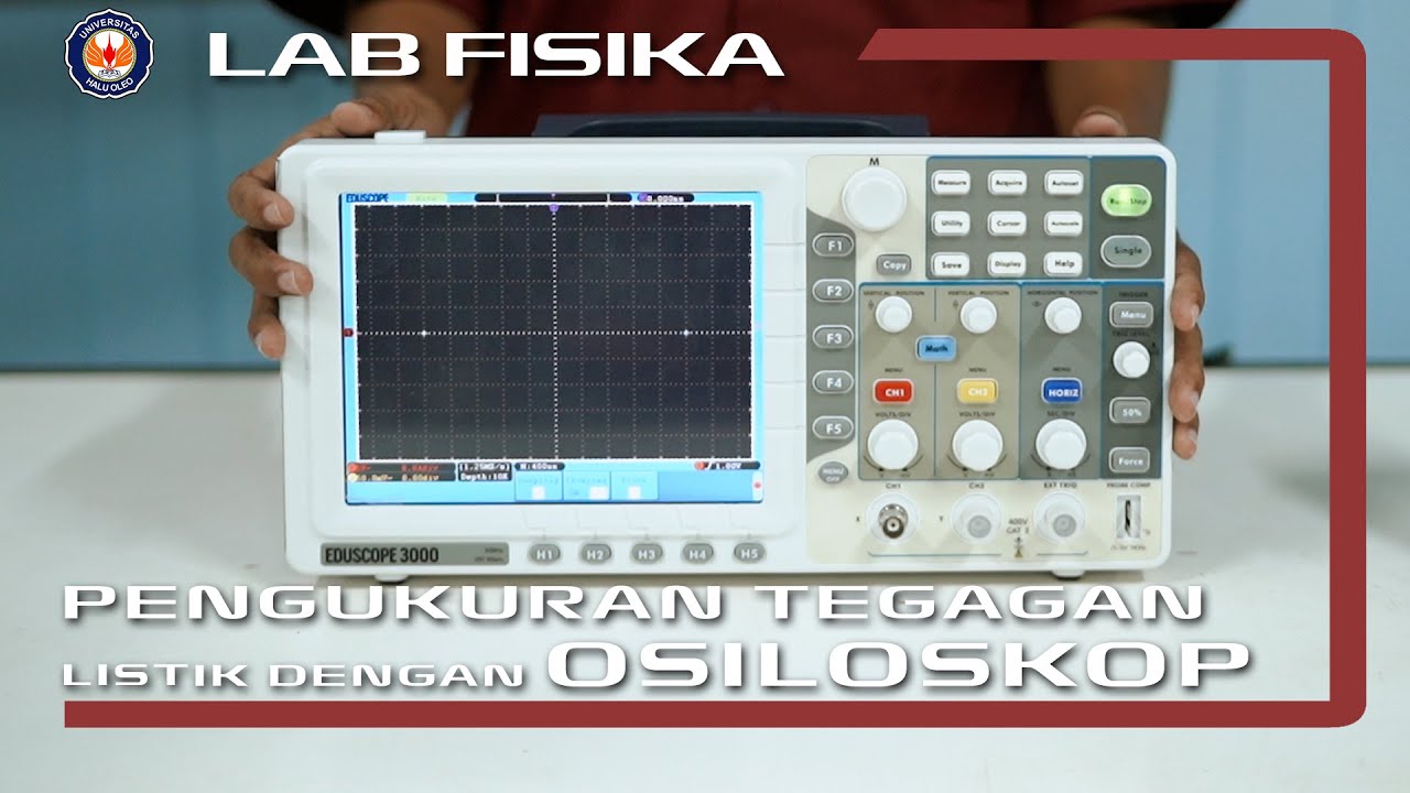
TLDRIn this instructional video, the process of measuring voltage waveforms using an oscilloscope is explored in depth. The presenter, Muhammad Fahrul Fauzi, walks through essential tools such as DC voltage batteries, signal generators, multimeters, and oscilloscopes. The video covers steps for calibration, measuring DC and AC voltages, and performing various signal operations like addition and subtraction. Practical exercises include analyzing sinusoidal signals and generating Lissajous patterns, along with phase difference calculations. The viewer learns hands-on techniques for accurate waveform analysis, useful in both academic and professional settings in electrical engineering.
Takeaways
- 😀 The video introduces the practical lab experiment for LFD Semester 2, focusing on shape measurement and voltage using an oscilloscope.
- 😀 The presenter is Muhammad Fahrul Fauzi, a student from the 2017 batch of Electrical Engineering.
- 😀 The primary equipment used includes a battery (DC voltage source), signal generators, a multimeter, and an oscilloscope.
- 😀 Two signal generators are used in the experiment to perform mathematical operations on the signals, either adding or subtracting them.
- 😀 Calibration of the oscilloscope is essential before starting the experiment to ensure accurate results and minimize noise.
- 😀 The oscilloscope’s settings, including vertical and horizontal positioning, voltage scaling, and time scale, are adjusted to display the voltage signals properly.
- 😀 The first experiment involves measuring the battery voltage using both a multimeter (DC voltage) and an oscilloscope.
- 😀 The multimeter reading for the battery voltage is 2.683 volts, while the oscilloscope reading shows a voltage of 2.7 volts.
- 😀 The second experiment explores measuring the voltage from a signal generator, with a fixed frequency of 1 kHz, while varying the amplitude of the signal.
- 😀 The multimeter and oscilloscope both provide RMS voltage readings, with measurements of 11.22V, 18.5V, and 17.88V as the amplitude varies.
- 😀 The final experiment involves creating Lissajous patterns with two signal generators and determining the phase difference between them using the oscilloscope.
- 😀 Mathematical operations like signal addition and subtraction are also performed on the oscilloscope to visualize the effect of phase differences, with examples of constructive and destructive interference.
Q & A
What is the purpose of the first experiment described in the video?
-The first experiment is aimed at measuring voltage from a DC battery using a multimeter and an oscilloscope, with a focus on accurately reading the voltage values for both DC and AC sources.
How is the oscilloscope calibrated before beginning the experiment?
-The oscilloscope is calibrated by connecting a BNC to crocodile clip cable, setting the DC coupling on channel one, and adjusting the oscilloscope's vertical and horizontal settings to remove noise and ensure accurate readings.
What is the significance of the 'auto' button on the oscilloscope during the experiment?
-The 'auto' button on the oscilloscope automatically adjusts the settings to display a stable waveform on the screen, making it easier to observe and measure voltage and signal characteristics.
How does a multimeter differ from an oscilloscope in terms of measuring voltage?
-A multimeter measures the average or RMS voltage value, whereas an oscilloscope provides a real-time graphical display of the waveform, showing voltage fluctuations over time and allowing for detailed analysis of both AC and DC signals.
What role does the signal generator play in the experiments?
-The signal generator produces sine wave signals with adjustable frequencies and amplitudes, which are used to test and analyze the behavior of both AC and DC voltages under different conditions during the experiment.
What does the term 'VRMS' refer to in the context of this experiment?
-VRMS refers to the root mean square voltage, which is a measure of the effective voltage of an AC signal. It is used to quantify the amplitude of a waveform, representing the equivalent DC voltage that would produce the same power dissipation in a resistor.
How are frequency and amplitude varied in the second part of the experiment?
-In the second part of the experiment, the frequency and amplitude of the signal generator are adjusted. The first step is to keep the frequency constant (1 kHz) while varying the amplitude, and then in the second part, the amplitude is fixed while varying the frequency.
Why is it important to use both the multimeter and oscilloscope in this experiment?
-Using both the multimeter and oscilloscope allows for a more comprehensive understanding of the signal. The multimeter gives accurate voltage readings (especially RMS), while the oscilloscope provides a visual representation of the waveform's shape and behavior, which helps in understanding the signal's characteristics.
What is the Lissajous pattern, and how is it used in the experiment?
-The Lissajous pattern is a visual representation of the relationship between two sinusoidal waveforms. In the experiment, it is used to observe the phase difference between two signals generated by different signal generators, with the frequency ratios providing specific patterns.
How is the phase difference between two signals determined using the Lissajous pattern?
-The phase difference is determined by adjusting the Lissajous pattern on the oscilloscope and using the cursor measurements to find the distance between two points on the waveform. The difference in the horizontal and vertical positions of the cursors provides the phase shift between the two signals.
Outlines

This section is available to paid users only. Please upgrade to access this part.
Upgrade NowMindmap

This section is available to paid users only. Please upgrade to access this part.
Upgrade NowKeywords

This section is available to paid users only. Please upgrade to access this part.
Upgrade NowHighlights

This section is available to paid users only. Please upgrade to access this part.
Upgrade NowTranscripts

This section is available to paid users only. Please upgrade to access this part.
Upgrade NowBrowse More Related Video

Cara Mengalibrasi (Kalibrasi) Osiloskop Analog - 2122600059

Simulasi Multisim Labsheet 1 Penyearah Gelombang Dengan Menggunakan Jembatan Dioda.
Percobaan Pengukuran Tegangan Listrik Dengan Osiloskop | Praktikum Fisika Dasar 2

How to Read an Oscilloscope - GCSE and A Level Physics

CARA MENGGUNAKAN OSCILLOSCOPE DIGITAL HANTEK DSO5102P

Fluke MDA-500 Demonstration using DC Voltage
5.0 / 5 (0 votes)