Nilai Umum K pada Batang Tekan Struktur Baja | Lightboard
Summary
TLDRIn this video, the presenter explores the calculation of effective length factors (k) for columns in steel structures, specifically focusing on the factors that influence column slenderness. The discussion highlights the importance of the column's effective length factor (k) and its dependence on the type of column support (hinged, fixed, or combined). Real-world examples of steel portal frames are used to demonstrate the variation in k values, based on the stiffness of beams compared to columns. The video also delves into how to calculate k values through a simplified approach, emphasizing the relationship between beam and column stiffness.
Takeaways
- 😀 The slenderness factor for columns consists of three key components: effective length factor (k), column length, and radius of gyration.
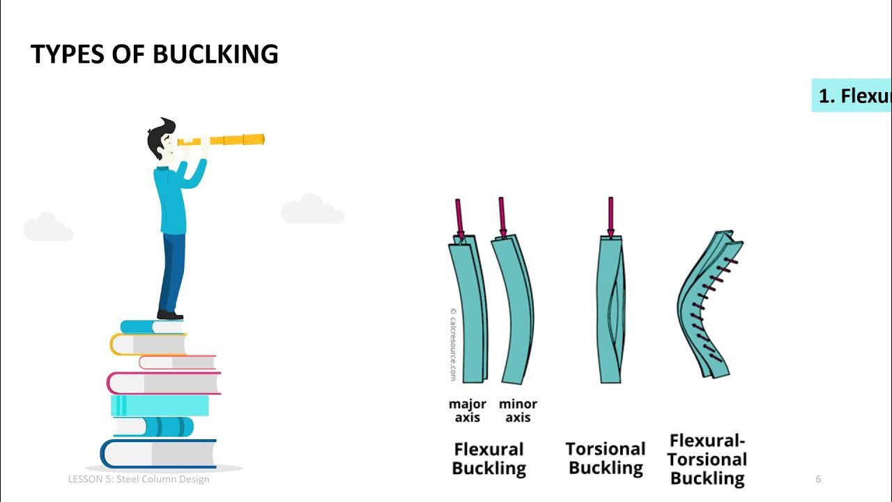
- 😀 The effective length factor (k) is influenced by the column's placement, whether it's a hinge, fixed, roller, or a combination of these placements.
- 😀 Different placement scenarios (e.g., hinge-hinge, fixed-fixed) result in different values for the effective length factor, as described in tables presented earlier.
- 😀 Real-world column placements are often more complex than idealized cases, so it's necessary to account for the actual stiffness of beams and columns when calculating the effective length factor.
- 😀 In portal frame structures, lateral movement needs to be considered when determining the effective length factor for the columns.
- 😀 For a column with greater stiffness than the beam, the column will behave more like it’s fixed (k value approaching 0.65), while if the column is weaker, it behaves more like a hinge (k value approaching 1).
- 😀 The relationship between column stiffness and beam stiffness is crucial in determining the effective length factor and can be quantified using a stiffness ratio (G).
- 😀 The modulus of elasticity, moment of inertia of both beams and columns, and the length of each element all affect the calculation of the effective length factor.
- 😀 The effective length factor (k) is determined by the stiffness ratio between the column and the beam (denoted as G), with a specific focus on how these properties impact the column's stability.
- 😀 Graphical methods can be used to determine the effective length factor by plotting stiffness ratios at key locations and finding the point of intersection to calculate k.
- 😀 A clear understanding of how stiffness in columns and beams influences the overall structure is essential for accurate calculations of column stability and effective length factor.
Q & A
What is the focus of the video discussed in the transcript?
-The video focuses on the calculation of the effective length factor (k) in structural steel columns, specifically for compressive members, and the factors influencing it, such as column placement and stiffness.
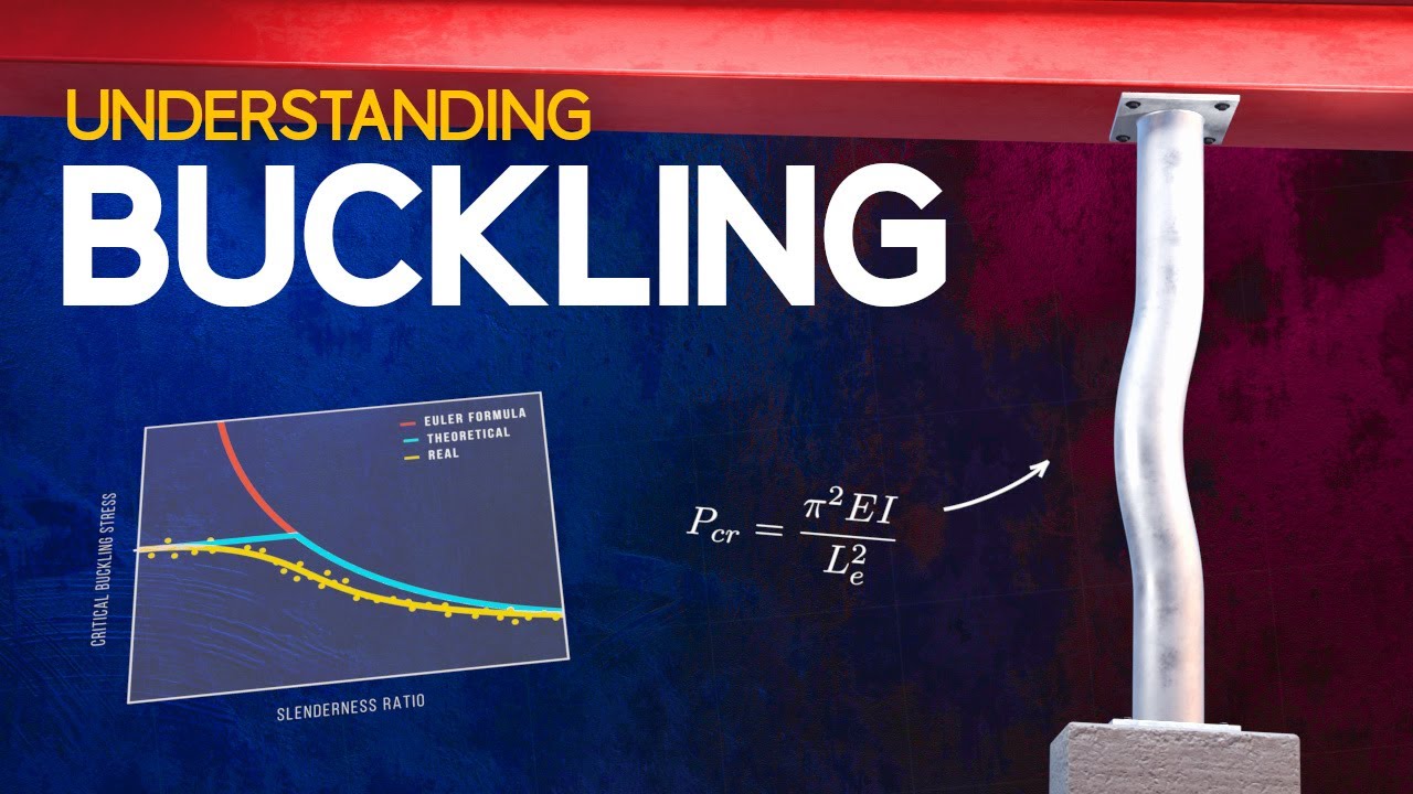
What is the effective length factor (k) and why is it important?
-The effective length factor (k) is a critical parameter used in the design of columns under axial compression. It accounts for the column's ability to resist buckling, and its value is influenced by the column's boundary conditions, such as whether the column ends are pinned, fixed, or free.
What are the three main factors that determine the slenderness of a column?
-The three main factors that determine the slenderness of a column are the effective length factor (k), the length of the column, and the radius of gyration of the column's cross-section.
How does the column placement affect the value of the effective length factor (k)?
-The placement of the column—whether it is pinned, fixed, or in a combination of these—affects the effective length factor (k). For example, a pinned-pinned column has an effective length factor of 1, while a fixed-fixed column might have a factor closer to 0.5.
What challenges arise when calculating the effective length factor for real-world columns compared to simplified cases?
-In real-world scenarios, columns are often not isolated or idealized as single elements, unlike in simplified textbook examples. Instead, they may be influenced by surrounding beams or other structural elements, requiring a more complex calculation of the effective length factor that considers the stiffness of both the column and the beams.
What is the role of the stiffness of the beams in calculating the effective length factor?
-The stiffness of the surrounding beams significantly affects the calculation of the effective length factor. If the beams are weak compared to the column, the column may behave as if it is pinned at both ends. However, if the beams are sufficiently stiff, the column may behave as if it is fixed at the ends.
What is the idealized column end placement in the video’s example?
-In the video example, one column end is assumed to be pinned, while the other end might either be fixed or pinned, depending on the specific structural context. The calculation of the effective length factor (k) depends on these boundary conditions.
What does the symbol 'G' represent in the calculation of the effective length factor?
-'G' represents the stiffness ratio between the column and the beam. It is defined as the ratio of the column's stiffness to the beam's stiffness and plays a key role in determining the value of the effective length factor (k).
How can the value of 'G' be simplified in the case where the column and beam are made of the same material?
-If the column and beam are made from the same material, the stiffness ratio 'G' can be simplified by using the formula, where 'G' is proportional to the ratio of the column's moment of inertia to the beam's moment of inertia, adjusted by the respective lengths of the column and beam.
What method is used to calculate the effective length factor (k) in the video?
-The effective length factor (k) is calculated by considering the stiffness of both the column and the beams at a given joint or connection point. A graphical method is used, where values of 'G' at different connection points are plotted and the effective length factor (k) is determined based on these values.
Outlines

This section is available to paid users only. Please upgrade to access this part.
Upgrade NowMindmap

This section is available to paid users only. Please upgrade to access this part.
Upgrade NowKeywords

This section is available to paid users only. Please upgrade to access this part.
Upgrade NowHighlights

This section is available to paid users only. Please upgrade to access this part.
Upgrade NowTranscripts

This section is available to paid users only. Please upgrade to access this part.
Upgrade NowBrowse More Related Video


5.0 / 5 (0 votes)