BIM workflow untuk Struktur: Revit dan Robot Structural Analysis
Summary
TLDRThis video demonstrates the use of structural analysis software to automate the design and verification of steel and concrete structures. The process includes importing AutoCAD 2D drawings, defining loads, analyzing structural members, and designing steel connections and concrete elements. The software simplifies tasks such as load combination, stability checks, and generates automated reports and drawings, making it a valuable tool for structural engineers. The detailed walkthrough shows how to use these features to streamline the structural design process, ensuring accuracy and efficiency in engineering projects.
Takeaways
- 😀 The script discusses the ease of using software for structural analysis in construction, offering an automated approach to design and modeling.
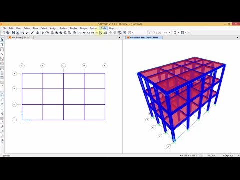
- 😀 It highlights the use of structural analysis software (Robot Structural Analysis) to directly import and analyze models, saving time in the design process.
- 😀 The integration of AutoCAD models into the software allows engineers to skip the need for rebuilding models from scratch, streamlining the workflow.
- 😀 The script mentions the automatic incorporation of loads such as dead load, live load, and snow load in the analysis model.
- 😀 Structural engineers can define load combinations and use design codes automatically in the software, ensuring compliance with standards.
- 😀 After performing the analysis, results such as forces, moments, and stress in structural members can be reviewed and visualized for easier interpretation.
- 😀 The script describes how instability in structural members can be checked, with a tool to identify and resolve issues related to size and stability.
- 😀 Steel structure connections can be designed and analyzed, including verification of connection types for strength and stability.
- 😀 Concrete design features are also integrated into the software, allowing engineers to check and verify concrete elements according to design codes.
- 😀 The script emphasizes the ability to generate reports and detailed drawings for both steel and concrete structures, which can be exported for documentation purposes.
Q & A
What is the main focus of the transcript?
-The transcript primarily discusses the use of structural analysis software, specifically Robot Structural Analysis, for designing and analyzing both steel and concrete structures.
How does the software assist in structural design?
-The software allows for direct import of models from AutoCAD, automatic generation of analysis models, and the inclusion of various load types like dead load, live load, and snow load. It also automates the creation of load combinations and factor adjustments based on the selected design code.
What types of structures are being analyzed in the video?
-The video focuses on the analysis of both steel and concrete structures, including elements like steel beams, concrete slabs, and their respective connections.
What does the 'instability' issue in the steel structure refer to?
-Instability refers to situations where the steel member does not meet the required stability criteria. This is identified through warnings such as yellow (check) and red (instability) signals, which help the engineer verify and adjust the design.
What role do 'connection design' tools play in the software?
-The software provides tools to design and analyze steel connections. Engineers can select members to design the connections and verify their adequacy, with the ability to export this data as part of a comprehensive report.
How does the software handle the design of concrete elements?
-For concrete design, the software supports the definition of the design code, such as IC31, and offers detailed calculations and element design based on input parameters like force and moment values.
What type of data is displayed for concrete design calculations?
-The concrete design output includes detailed calculations, such as reinforcement required, element dimensions, and cover requirements. Additionally, detailed reports and graphical outputs are generated.
Can the software generate 2D drawings from structural models?
-Yes, the software can generate 2D drawings automatically, such as wall details and reinforcement specifications. These drawings are useful for generating reports and ensuring accurate design implementation.
What is the significance of load combination in the software?
-Load combinations are essential for structural safety as they define how different load types, such as dead load, live load, and environmental loads, interact. The software automates the creation of these combinations based on the design code.
How does the software help engineers save time in structural design?
-The software automates many aspects of the design process, including the generation of analysis models, load combinations, and connection designs, thereby reducing the time needed for manual calculations and model creation.
Outlines

This section is available to paid users only. Please upgrade to access this part.
Upgrade NowMindmap

This section is available to paid users only. Please upgrade to access this part.
Upgrade NowKeywords

This section is available to paid users only. Please upgrade to access this part.
Upgrade NowHighlights

This section is available to paid users only. Please upgrade to access this part.
Upgrade NowTranscripts

This section is available to paid users only. Please upgrade to access this part.
Upgrade Now


5.0 / 5 (0 votes)