#4 How to control the world outside?
Summary
TLDRIn this lesson, Miro Samek demonstrates how to blink an LED on the Stellaris Launchpad board. The tutorial covers setting up the IAR project, understanding the microcontroller’s memory map, enabling the GPIO block, and configuring pins for digital output. By using pointers in C, students learn to control the LED's red, green, and blue colors. The lesson concludes with tips on implementing an endless loop for blinking and adjusting the program's speed to make the blinking visible. This foundational exercise in embedded systems programming is an essential milestone for beginners.
Takeaways
- 😀 Download the User Manual of the Stellaris Launchpad board for essential information on connections and hardware components.
- 😀 The User LED on the board is connected to GPIO pins (F1, F2, F3), which control the Red, Green, and Blue LED components respectively.
- 😀 The manual provides the schematics of the board, showing how components are connected to the microcontroller, including the LED's transistor controls.
- 😀 In this lesson, the focus is on setting up the IAR project and ensuring that the debugger is configured correctly, especially for the TI Stellaris interface.
- 😀 Understanding the address mapping and memory space of the microcontroller is crucial for interacting with hardware like the LED.
- 😀 The datasheet for the microcontroller is essential for understanding the full memory map, including how GPIO ports are organized.
- 😀 Clock gating, a method of saving power by turning off specific hardware blocks, needs to be disabled for GPIO-F to work.
- 😀 You must enable GPIO-F by modifying the clock gating control register, then configure the GPIO-F pins as outputs for controlling the LED.
- 😀 By using the debugger, you can directly manipulate memory addresses to control hardware components, such as turning the LED on and off.
- 😀 The key to controlling the LED is writing specific values to memory addresses associated with GPIO ports, a skill that will be coded in C using pointers.
- 😀 The LED can be blinked by writing a program that continually toggles the LED on and off in a loop, with the added challenge of incorporating a delay to make the blinking visible.
Q & A
What is the main objective of this lesson?
-The main objective of this lesson is to teach how to blink an LED on the Stellaris Launchpad board using embedded systems programming techniques.
What is recommended for students who don't have the Stellaris Launchpad board?
-Students who do not have the Stellaris Launchpad board are encouraged to follow along using a simulator, though their debugger views will differ, and they won't be able to see the LED blink.
What is GPIO, and how does it relate to the User LED on the board?
-GPIO stands for General Purpose Input-Output. The User LED on the Stellaris Launchpad is connected to GPIO pins, which allow the LED to be controlled through outputs labeled LED_R, LED_G, and LED_B for Red, Green, and Blue components.
Why is the 'clock-gating' technique important in embedded systems?
-Clock-gating is a power-saving technique that turns off specific hardware blocks to save energy. In this case, the GPIO-F block, which controls the LED, must be activated by enabling its clock before it can be used.
What is the significance of the memory map in the microcontroller?
-The memory map outlines the layout of various memory regions in the microcontroller, including flash memory, RAM, and peripheral registers. Understanding the memory map is crucial for correctly configuring and accessing the hardware components, such as GPIO.
What is the purpose of setting specific bits in the GPIO-F registers?
-Setting specific bits in the GPIO-F registers allows configuring the GPIO pins for the LED as outputs and enables digital functionality, thereby controlling the LED's color and behavior.
How do you activate the GPIO-F hardware block?
-To activate the GPIO-F hardware block, you must set bit 5 in the clock-gating control register. This can be done using the debugger and the memory view, which involves writing the appropriate value to the register.
Why does the red LED light up when bit 1 of the GPIO-F data register is set?
-Setting bit 1 of the GPIO-F data register to 1 corresponds to turning on the red LED. This is because the red LED is connected to GPIO pin 1, and writing a high value to this register drives the red LED on.
What issue arises when the program is run at full speed without any delays?
-When the program is run at full speed, the LED appears to stay on all the time because the blinking is too fast for the human eye to notice. To resolve this, a delay must be introduced to slow down the program and make the blinking visible.
How can the program be modified to include a delay between LED on and off states?
-A delay can be implemented using a counting while-loop, which wastes CPU cycles and controls how long the LED stays on or off. The upper limit of the while-loop determines the duration of the delay.
Outlines

This section is available to paid users only. Please upgrade to access this part.
Upgrade NowMindmap

This section is available to paid users only. Please upgrade to access this part.
Upgrade NowKeywords

This section is available to paid users only. Please upgrade to access this part.
Upgrade NowHighlights

This section is available to paid users only. Please upgrade to access this part.
Upgrade NowTranscripts

This section is available to paid users only. Please upgrade to access this part.
Upgrade Now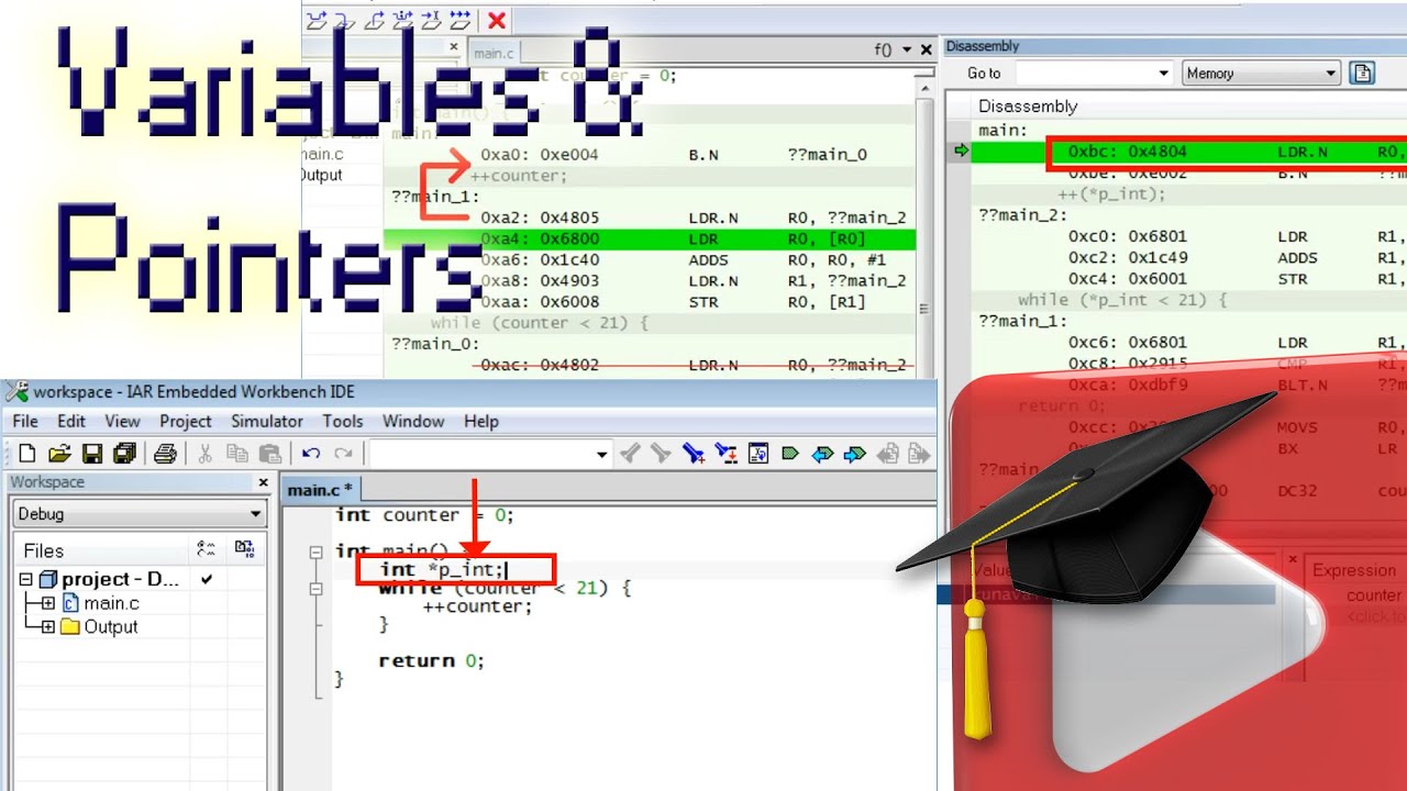


5.0 / 5 (0 votes)