Tutorial Penyearah Setengah Gelombang menggunakan Multisim
Summary
TLDRIn this tutorial, the group demonstrates how to build a half-wave rectifier circuit using MultiSim. The process begins by introducing the necessary components such as the AC power supply, transformer, diodes, resistor, multimeter, and oscilloscope. The team explains how to connect the components, perform measurements, and adjust the circuit for accurate readings. They delve into the working principle of the half-wave rectifier, illustrating how the diodes convert AC to DC voltage. The video also includes a detailed explanation of the results and calculations, providing a thorough understanding of the circuit's functionality.
Takeaways
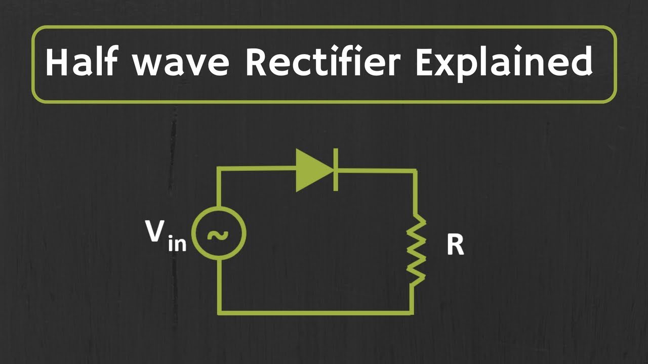
- 😀 The tutorial demonstrates how to build a half-wave rectifier circuit using MultiSim software.
- 😀 The main components used in the circuit are an AC power source, transformer, diode, resistor, and measuring instruments like a multimeter and oscilloscope.
- 😀 The AC power source is set to 220V with a frequency of 50Hz.
- 😀 A transformer with a 10:1 step-down ratio is used to reduce the AC voltage from 220V to 22V.
- 😀 The diode used in the circuit is a germanium diode with a forward voltage of 0.7V, which allows only the positive half of the AC signal to pass through.
- 😀 The multimeter is used to measure the voltage across different parts of the circuit, including the transformer and resistor.
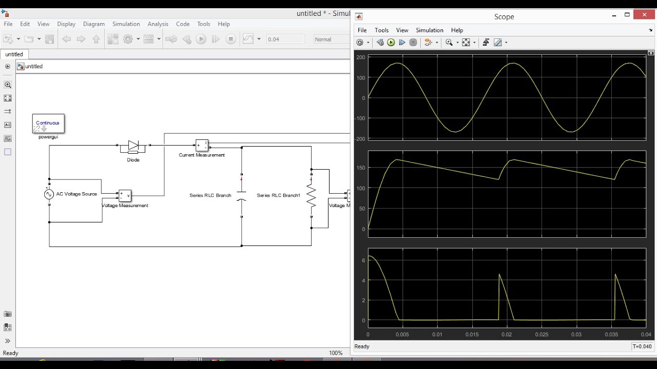
- 😀 The oscilloscope is used to visualize the waveform, showing the rectified output of the circuit.
- 😀 The process of rectification results in a pulsating DC output, as the negative half of the AC signal is blocked by the diode.
- 😀 Theoretical calculations estimate the output voltage to be around 9.9V, which closely matches the practical results (9.5V) observed in the simulation.
- 😀 The tutorial emphasizes the importance of understanding the half-wave rectification process, where the diode only allows the positive half of the waveform to pass through, turning the AC input into DC output.
Q & A
What is the purpose of the video tutorial?
-The purpose of the video tutorial is to demonstrate how to create a half-wave rectifier circuit using the MultiSim application.
What components are required to build the half-wave rectifier circuit?
-The components required are a 220V AC power source with a frequency of 50Hz, a transformer with a 10:1 ratio, a germanium diode with a 0.7V rating, a 1kΩ resistor, a multimeter, and an oscilloscope.
What is the role of the transformer in the half-wave rectifier circuit?
-The transformer steps down the AC voltage from 220V to 22V, which is used as the input for the rectifier circuit.
Why is a germanium diode used in the circuit?
-A germanium diode is used because it has a lower forward voltage drop (0.7V), making it ideal for rectification purposes in the circuit.
How does the diode affect the waveform in the half-wave rectifier?
-The diode cuts off the negative half of the AC waveform, allowing only the positive half to pass through, thereby converting the AC signal into a pulsating DC signal.
What does the oscilloscope measure in this setup?
-The oscilloscope measures the output waveform after the rectifier to observe the change from an AC to a pulsating DC signal.
What is the significance of the resistor in the circuit?
-The resistor is used to limit the current flow in the circuit and ensure that the components, especially the diode, do not get damaged due to excessive current.
What does the multimeter measure in this setup?
-The multimeter is used to measure the DC voltage at different points in the circuit, including across the load resistor and at the secondary side of the transformer.
What is the observed result on the multimeter after the rectification process?
-The multimeter shows a DC voltage of approximately 22V and 9.9V at different measurement points in the circuit, confirming the rectification of the AC signal.
What is the theoretical explanation behind the operation of the half-wave rectifier?
-In a half-wave rectifier, during the positive half-cycle of the AC signal, the diode is forward biased, allowing current to flow through the load. During the negative half-cycle, the diode is reverse biased, blocking the current, and only the positive half of the signal is passed as DC output.
Outlines

This section is available to paid users only. Please upgrade to access this part.
Upgrade NowMindmap

This section is available to paid users only. Please upgrade to access this part.
Upgrade NowKeywords

This section is available to paid users only. Please upgrade to access this part.
Upgrade NowHighlights

This section is available to paid users only. Please upgrade to access this part.
Upgrade NowTranscripts

This section is available to paid users only. Please upgrade to access this part.
Upgrade NowBrowse More Related Video

Half-Wave vs Full-Wave Rectifiers - Electronics Basics 19

Simulasi Multisim Labsheet 1 Penyearah Gelombang Dengan Menggunakan Jembatan Dioda.

Simulasi Penyearah Setengah Gelombang & Gelombang Penuh PROTEUS 8 || Merangkai Penyearah Dioda

MODUL1 PENYEARAH 1PHASE (HALF WAVE DAN FULL WAVE) MENGGUNAKAN SIMULINK MATLAB
Half Wave Unctrolled Rectifier with C filter Matlab Simulink
Half wave Rectifier Explained
5.0 / 5 (0 votes)