TUTORIAL - CARA KONFIGURASI VLAN PADA CISCO PACKET TRACER (UNTUK PEMULA)
Summary
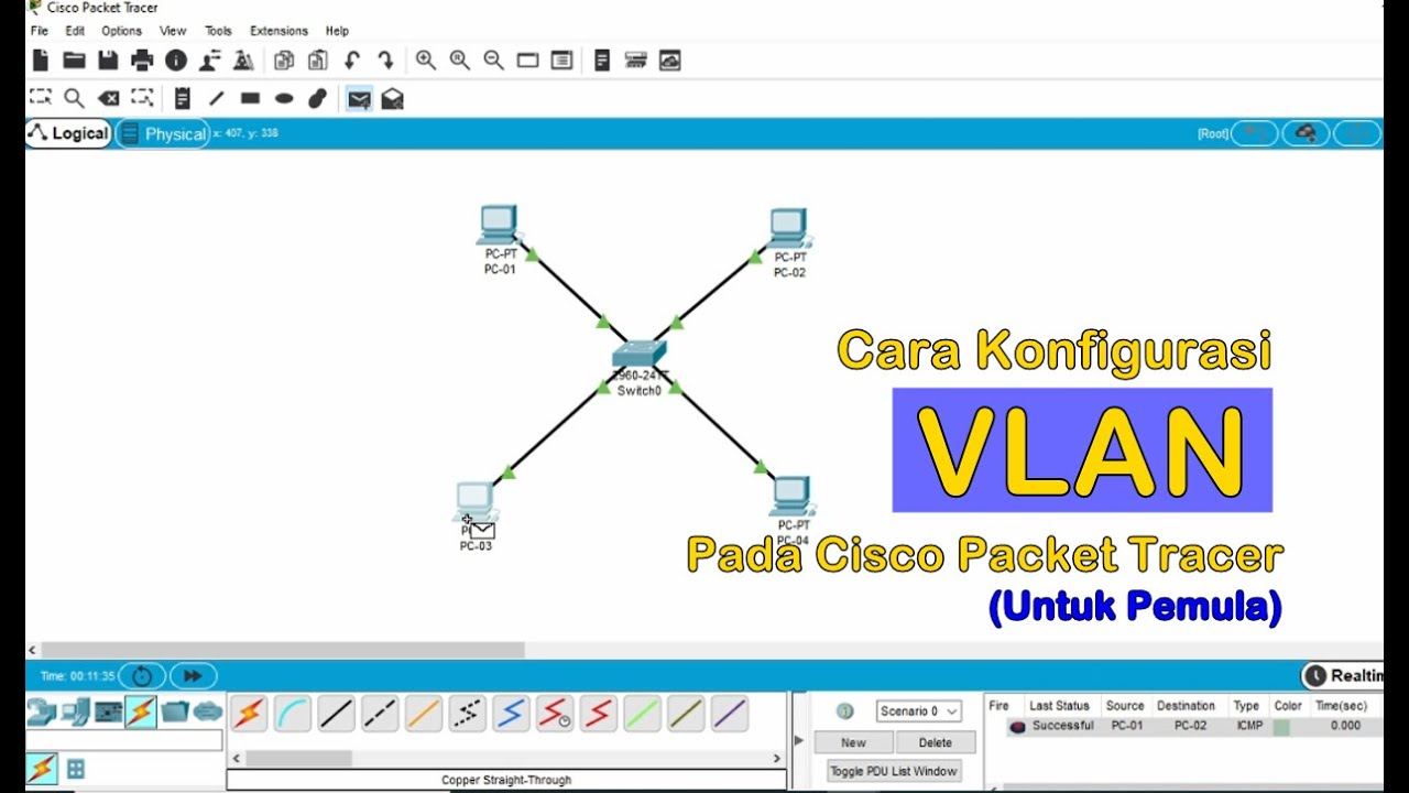
TLDRIn this tutorial, Riswandi demonstrates how to configure VLANs using Cisco Packet Tracer. The video explains the concept of VLANs, showing how to create and assign them to devices such as PCs and switches. The configuration steps include setting up VLANs 100 and 200, assigning static IP addresses, and testing connectivity between devices within the same VLAN and across different VLANs. The tutorial highlights the importance of VLANs in logically segmenting networks, even when devices are physically connected to the same switch. This step-by-step guide is perfect for beginners looking to understand VLAN configuration.
Takeaways
- 😀 The video introduces how to configure VLANs (Virtual Local Area Networks) using Cisco Packet Tracer.
- 😀 Cisco Packet Tracer is a network simulation tool used for creating and testing network configurations.
- 😀 VLANs allow computers and users to communicate within a localized network, simulating a LAN environment.
- 😀 The speaker demonstrates how to create and configure a basic VLAN network with devices like switches and PCs.
- 😀 The configuration starts with adding a switch and connecting several PCs to form different VLANs.
- 😀 The switch used is the Cisco 2950T, and the VLANs are named VLAN 100 and VLAN 200.
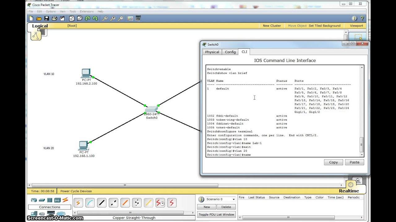
- 😀 VLANs are configured by accessing the switch's command line interface and typing the necessary commands to assign ports to specific VLANs.
- 😀 The speaker configures two VLANs: VLAN 100 for PC1 and PC2, and VLAN 200 for PC3 and PC4.
- 😀 Communication between devices on different VLANs is not possible without a router or Layer 3 switch for routing between VLANs.
- 😀 IP configuration is performed on each PC, with static IP addresses set to allow communication within the same VLAN.
- 😀 The video demonstrates a successful ping between devices in the same VLAN but fails between devices in different VLANs, highlighting the need for inter-VLAN routing.
Q & A
What is the main topic of the video?
-The main topic of the video is configuring VLANs (Virtual Local Area Networks) in Cisco Packet Tracer, a network simulation software.
What software is used in the video tutorial?
-The software used in the tutorial is Cisco Packet Tracer, which is used for simulating network configurations and devices.
What does VLAN stand for and what is its purpose?
-VLAN stands for Virtual Local Area Network. It is used to logically segment devices into different networks within a switch, even if they are physically connected to the same switch.
How does the video define VLAN in the context of the tutorial?
-In the video, VLAN is described as a network that allows computers and users to communicate as if they are in the same LAN, regardless of their physical location within the network.
What are the steps involved in creating VLANs in Cisco Packet Tracer?
-To create VLANs in Cisco Packet Tracer, you need to open the switch's CLI, enable configuration mode, create a VLAN with the command `vlan <vlan_id>`, and assign switch ports to the VLAN using the `switchport access vlan <vlan_id>` command.
How are the devices connected in the simulation?
-In the simulation, devices such as PCs are connected to a Cisco switch using Ethernet cables. The devices are then assigned to specific VLANs for network segmentation.
What is the significance of using `switchport mode access` in the VLAN configuration?
-`switchport mode access` is used to set a switch port to access mode, which means it will be assigned to a single VLAN and can only communicate with devices within that VLAN.
What IP addresses are assigned to the PCs in the tutorial?
-The IP addresses assigned in the tutorial are as follows: PC 1 (VLAN 100) gets `192.168.1.1`, PC 2 (VLAN 100) gets `192.168.1.2`, PC 3 (VLAN 200) gets `192.168.2.1`, and PC 4 (VLAN 200) gets `192.168.2.2`.
What happens when a ping is attempted between devices on different VLANs?
-When a ping is attempted between devices on different VLANs, such as between PC 1 and PC 3, it will fail because devices on separate VLANs cannot communicate directly without a router.
Why can't PC 1 communicate with PC 3 despite being connected to the same physical switch?
-PC 1 cannot communicate with PC 3 because they are in different VLANs. Even though they are physically connected to the same switch, the VLANs logically separate them, preventing direct communication.
Outlines

This section is available to paid users only. Please upgrade to access this part.
Upgrade NowMindmap

This section is available to paid users only. Please upgrade to access this part.
Upgrade NowKeywords

This section is available to paid users only. Please upgrade to access this part.
Upgrade NowHighlights

This section is available to paid users only. Please upgrade to access this part.
Upgrade NowTranscripts

This section is available to paid users only. Please upgrade to access this part.
Upgrade NowBrowse More Related Video
Tutorial - Cara Konfigurasi VLAN pada Cisco Packet Tracer (Untuk Pemula)

TUTORIAL - KONFIGURASI VLAN PADA CISCO PACKET TRACER - 2022
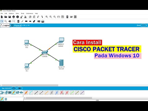
Tutorial - Cara Download & Install Cisco Packet Tracer pada Windows 10

Netzwerktutorial: Cisco Packet Tracer - Installation, Konfiguration & ein erster Aufbau
Single Switch VLAN in Packet Tracer
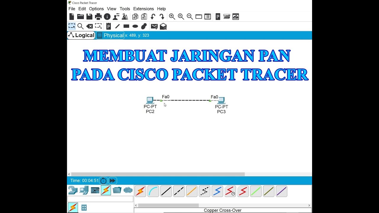
Membuat Jaringan PAN pada Cisco Packet Tracer
5.0 / 5 (0 votes)