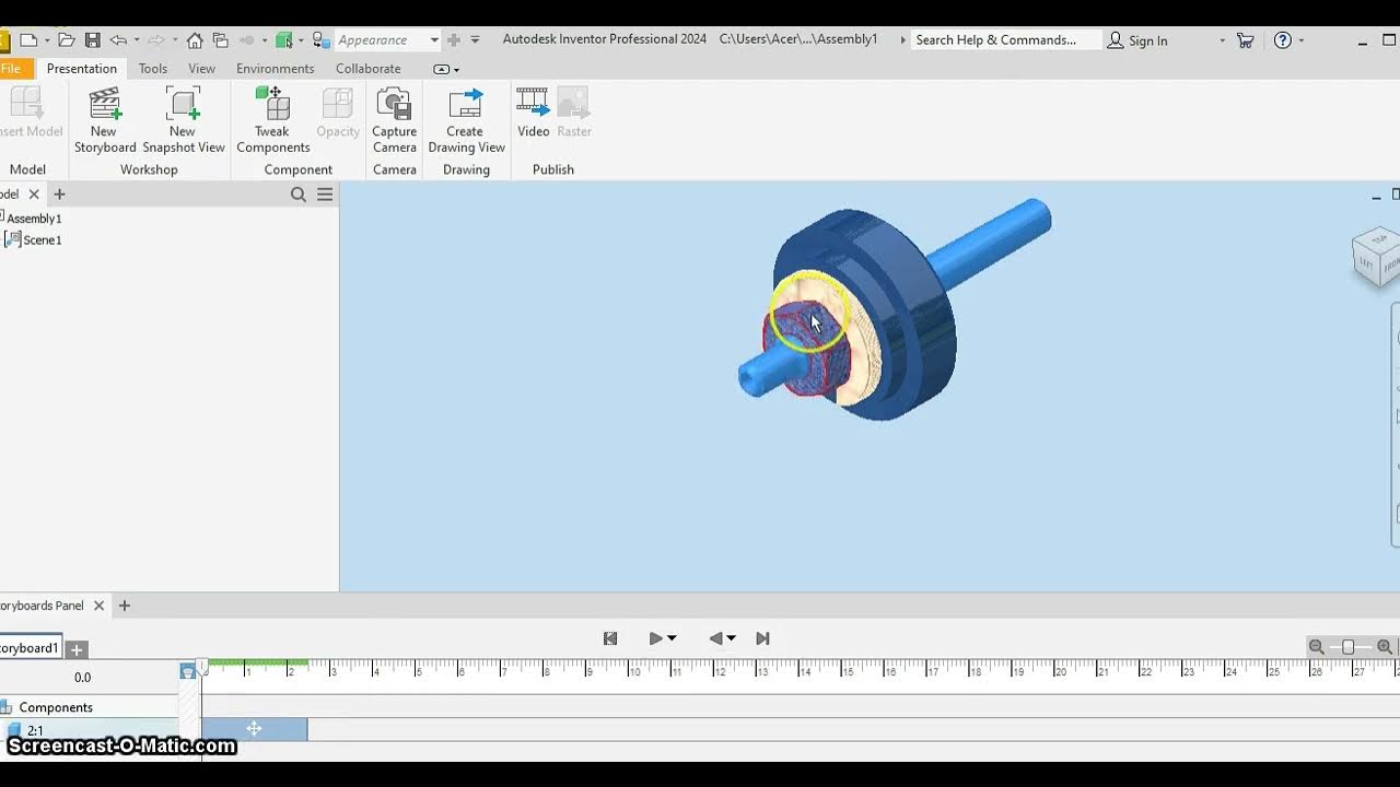
Tutorial Contoh Soal CSWA Assembly Connecting Rod
Summary
TLDRIn this tutorial, the presenter walks through an assembly CSWA example, focusing on the process of connecting components. The tutorial covers how to set units, insert components, and apply constraints like 'Mate' and 'Angle' to align parts correctly. It demonstrates how to handle different assembly features, such as creating and editing angles and distances, while also providing tips for tackling exam-related problems. The tutorial concludes with instructions on how to adjust the assembly for different configurations, ensuring clarity and precision in the process. The video is ideal for CSWA exam preparation.
Takeaways
- 😀 Switch the unit system to MM, GR, second before starting the assembly in SOLIDWORKS.
- 😀 Use the 'Insert Component' feature to add parts into the assembly.
- 😀 To replicate components, use the copy-paste shortcut (Ctrl + C, Ctrl + V).
- 😀 Mate circular faces of the components to align them accurately in the assembly.
- 😀 Ensure to align the outer surfaces of components using the 'Mate' tool.
- 😀 Set the angle between parts to 21 degrees using the 'Mate' tool and specify the angle value directly.
- 😀 Adjust the distance between parts to a specified value (e.g., 14mm) using the 'Mate' tool.
- 😀 Use the 'Evaluate' tool to measure the normal distance between two selected faces.
- 😀 Edit mate features later if the problem changes (e.g., different angle or distance).
- 😀 After completing all mates and adjustments, verify the assembly by checking its alignment and measurements.
- 😀 The tutorial is designed to help CSWA exam candidates understand how to solve assembly problems effectively in SOLIDWORKS.
Q & A
What is the first step in the assembly process for the Connecting Root task?
-The first step is to set your units from IPS to mm, g, and seconds to ensure consistency during the assembly.
How do you insert the required components into the assembly?
-You insert components by selecting 'Insert Component' in the assembly environment. After that, open the relevant file that contains the components, select all, and click 'Open'.
What should be done after opening the assembly components?
-Once the components are loaded, you need to start positioning and mating them based on the requirements of the task.
What is the purpose of copying and pasting components during the assembly process?
-Copying and pasting components helps in creating the necessary duplicate parts for the assembly, ensuring each component is in the correct position as required by the design.
How do you mate the components together in the assembly?
-To mate the components, you align their faces or edges using the 'Mate' function. This will fix their relative positions in the assembly according to the desired alignment.
What should you do if components in the assembly are not aligned correctly?
-You can move the components slightly to better align them, making the assembly process smoother. After repositioning, reapply the required mates.
How is the angle between components set during the assembly?
-The angle between components is set using the 'Mate' feature. If an angle is provided (e.g., 21 degrees), select the angle mate and input the exact value to ensure the components are aligned as per the design.
What is the significance of the distance 'a' in the assembly, and how is it set?
-The distance 'a' represents the separation between two outer surfaces of components. This is set using the 'Mate' function, where you input the required distance (e.g., 14 mm).
How can the distance 'x' be measured in the assembly?
-To measure the distance 'x', go to the 'Evaluate' tab, select 'Measure,' and click on the relevant faces to measure the 'Normal Distance' between them.
What should be done if the angle or distance values change in subsequent tasks?
-If the angle or distance values change, you can go back to the relevant mate, select it, and use the 'Edit Feature' option to modify the angle or distance according to the new specifications.
Outlines

This section is available to paid users only. Please upgrade to access this part.
Upgrade NowMindmap

This section is available to paid users only. Please upgrade to access this part.
Upgrade NowKeywords

This section is available to paid users only. Please upgrade to access this part.
Upgrade NowHighlights

This section is available to paid users only. Please upgrade to access this part.
Upgrade NowTranscripts

This section is available to paid users only. Please upgrade to access this part.
Upgrade NowBrowse More Related Video

ARDUINO Project #001 : Mesin Penghitung Otomatis E18-D80NK
IPN MANDRIL
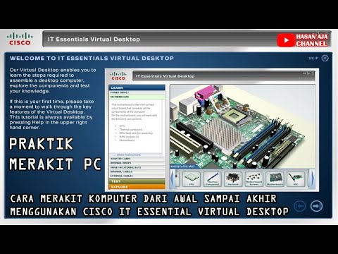
Cara Merakit Komputer Dari Awal Sampai Akhir Menggunakan Cisco IT Essentials Virtual Desktop

Multiboard Tile Learning Pack : Getting Started With Multiboard
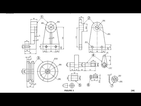
Assembly Drawing N3/7 August 2024/Part 1️⃣
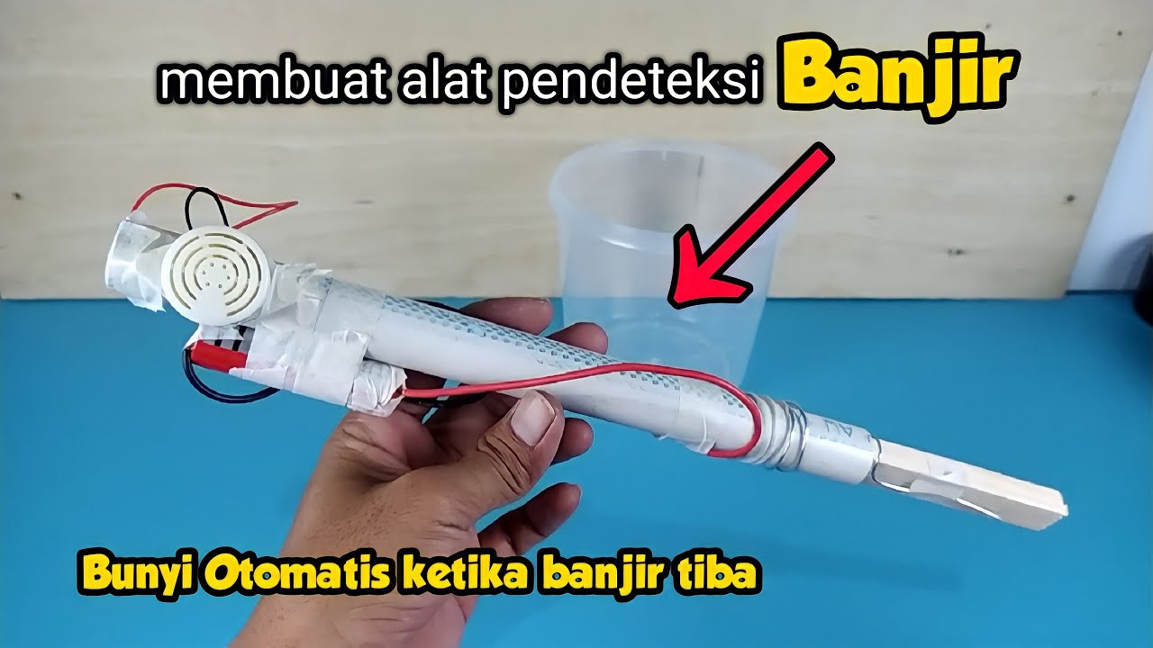
cara membuat alat PENDETEKSI BANJIR, kalian bisa buat sendiri dirumah !!!
5.0 / 5 (0 votes)