Ladder Logic Examples - PLC Programming Example for Practice
Summary
TLDRThis video explains the concepts of latching and unlatching in PLC programming using CX-Programmer. It demonstrates how different push buttons (PB1 to PB5) control pumps (Pump 1, Pump 2, Pump 3) through simple logic. Latching keeps pumps on even when buttons are released, while unlatching turns pumps off when a stop button is pressed. The tutorial includes step-by-step instructions on how to set up the inputs, outputs, and logic in the CX-Programmer, followed by a simulation to verify functionality. It's a practical guide for beginners learning automation and control logic.
Takeaways
- 😀 Latching and unlatching concepts were demonstrated using CX Programmer for controlling pumps.
- 😀 The first scenario explained how pressing the start push button (PB1) turns on pump 1, which stays on even if the push button is released (latching).
- 😀 The second scenario showed how pressing PB2 turns on pump 2, which remains on even if PB2 is released (latching).
- 😀 The third scenario clarified that pressing PB3 turns on pump 3, but the pump turns off when PB3 is released (no latching).
- 😀 The fourth scenario explained how pressing the stop push button (PB4) turns off pump 1 (unlatching) using a normally closed contact.
- 😀 The fifth scenario demonstrated that pressing PB5 turns off pump 2 (unlatching).
- 😀 The script highlights the importance of properly connecting inputs and outputs in CX Programmer for automation tasks.
- 😀 Latching and unlatching are key techniques to control the state of pumps based on the status of the push buttons.
- 😀 Inputs and outputs are organized clearly, with five inputs (push buttons) and three outputs (pumps).
- 😀 The script includes a step-by-step guide on how to implement these concepts in CX Programmer, including addressing and naming the inputs and outputs.
Q & A
What is the concept of latching in automation systems?
-Latching refers to keeping an output in an 'on' state even after the input signal (like a push button) is released. This is achieved by using a parallel contact in the circuit that maintains the output condition after the input is turned off.
How does unlatching differ from latching in the context of the script?
-Unlatching involves turning off an output as soon as the input (like a push button) is released. Unlike latching, where the output stays on, unlatching ensures that the output is off once the input signal is released.
What happens when Push Button 1 (PB1) is pressed in the system?
-When PB1 is pressed, Pump 1 turns on. Even if PB1 is released, Pump 1 remains on, demonstrating the latching concept.
What is the role of the normally open (NO) contact in the latching process?
-The normally open contact in a latching circuit is used to allow the output (such as a pump) to remain on even after the input signal is released. It is connected in parallel with the initial input to create this 'on' condition.
Why does the third push button (PB3) behave differently from the first two in terms of output?
-PB3 operates differently because its corresponding pump (Pump 3) turns on only while PB3 is pressed. Once PB3 is released, the pump turns off, indicating that this does not require latching but instead works as a temporary output control.
What does Push Button 4 (PB4) do in the system?
-PB4 is used to turn off Pump 1. It is configured with a normally closed contact, ensuring that when PB4 is pressed, it interrupts the current that is keeping Pump 1 on, thus turning it off.
How is Pump 2 turned off in the circuit?
-Pump 2 is turned off when PB5 is pressed. Similar to PB4, PB5 is associated with a normally closed contact, which when pressed, breaks the circuit and turns off Pump 2.
What is the significance of using a normally closed contact for stop push buttons?
-Normally closed contacts are used for stop push buttons because they ensure the circuit remains intact (allowing current to flow) until the button is pressed, at which point the contact opens and interrupts the current to turn off the corresponding pump.
What does the simulation in the script demonstrate?
-The simulation demonstrates how each push button interacts with the pumps. It shows how PB1 keeps Pump 1 on even when released, how PB2 keeps Pump 2 on, how PB3 turns Pump 3 on temporarily, and how PB4 and PB5 stop Pump 1 and Pump 2, respectively.
What are the key differences between Push Buttons 1, 2, and 3 in this example?
-PB1 and PB2 are used for latching their corresponding pumps on, meaning the pumps stay on even if the buttons are released. PB3, on the other hand, only turns the pump on while it is pressed, and turns it off when released, demonstrating a non-latching behavior.
Outlines

This section is available to paid users only. Please upgrade to access this part.
Upgrade NowMindmap

This section is available to paid users only. Please upgrade to access this part.
Upgrade NowKeywords

This section is available to paid users only. Please upgrade to access this part.
Upgrade NowHighlights

This section is available to paid users only. Please upgrade to access this part.
Upgrade NowTranscripts

This section is available to paid users only. Please upgrade to access this part.
Upgrade NowBrowse More Related Video
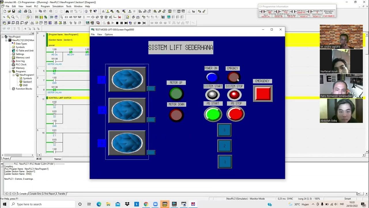
Simulasi Lift sederhana 3 Lantai dengan menggunakan PLC pada CX-Programmer dan CX-Designer
How to Program PLC Using Function Block Diagrams | OpenPLC

How to Download, Install, Program and simulate WPLSoft Delt PLC Software

Ladder Logic Diagrams for PLCs | Industrial Automation

Ladder Diagram Traffic Light Simpang 3 dengan Software CX-Programmer

1. Tutorial Pemrograman Sekuensial pada PLC
5.0 / 5 (0 votes)