Diagram Blok - 1- Pemodelan dengan diagram blok, komponen utama diagram blok, hubungan antar sistem
Summary
TLDRThe video explains the concept of block diagrams in control systems, focusing on transfer functions and differential equations. It discusses how functions and derivatives can be represented, introducing block diagrams that illustrate relationships between input and output. The system's components are broken down into signals, systems, summation points, and branching points. Different system configurations such as series, parallel, and closed-loop systems are also explored, demonstrating how signals are manipulated to produce the desired output. The key takeaway is understanding how these systems work together to control and optimize processes.
Takeaways
- 😀 The script discusses the concept of block diagrams, a fundamental topic in control systems.
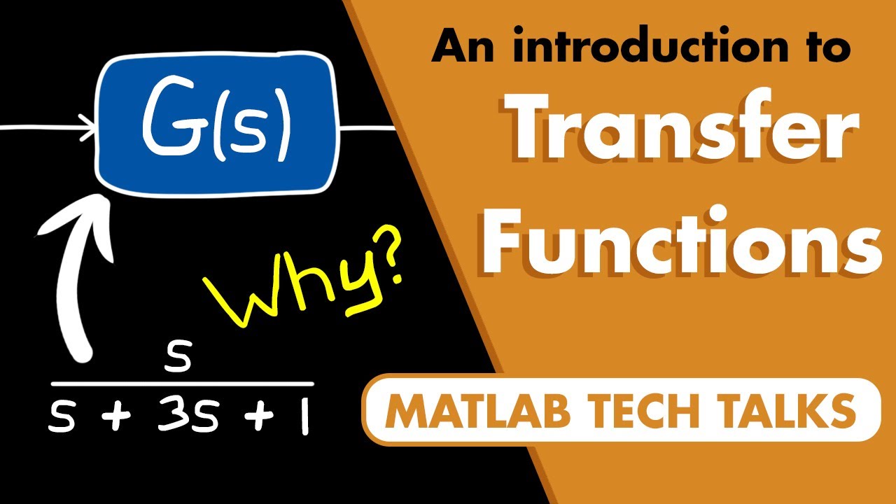
- 😀 Block diagrams represent relationships between input and output through a transfer function.
- 😀 A transfer function can be expressed using differential equations, with derivatives involving powers of 's'.
- 😀 The derivatives of a function take the form of powers of 's', such as s^2, s^3, s^n, which allows simplification in analysis.
- 😀 The transfer function is a key tool for understanding the input-output relationship in a system.
- 😀 Block diagrams consist of four main components: signals, systems, summing points, and branching points.
- 😀 Signals are the external inputs and feedback in the block diagram system.
- 😀 Systems in the block diagram represent control systems or processes that affect the signals.
- 😀 The script also describes serial, parallel, and closed-loop configurations for connecting systems in block diagrams.
- 😀 A serial system setup involves systems connected in sequence, with outputs from one system becoming inputs for the next.
- 😀 Parallel systems involve combining outputs of two systems and using a summing point for the final result.
- 😀 The closed-loop system involves feedback, with the output influencing the input through a feedback loop, which affects system performance.
Q & A
What is the main topic discussed in the transcript?
-The main topic of the transcript is the discussion of block diagrams in control systems, including transfer functions, feedback loops, and the mathematical representation of these systems using differential equations.
What is a transfer function in the context of control systems?
-A transfer function represents the relationship between the input and output of a system. It is typically expressed in terms of a ratio of polynomials in the Laplace transform variable 's', describing how the system responds to various inputs.
How are derivatives related to the transfer function as mentioned in the transcript?
-The derivatives of a function are used to express the system's response in terms of the Laplace transform. For example, the first derivative of a function is associated with sG(s), the second derivative with s^2G(s), and so on, leading to the general form of the transfer function.
What does the differential equation in the transcript represent?
-The differential equation in the transcript represents the relationship between the input and output of a system in terms of derivatives, which can then be transformed into a transfer function for analysis in the Laplace domain.
What are the components of a block diagram in control systems?
-A block diagram typically consists of four main components: signals, systems, summing points, and branching points. These components help to visualize the flow of signals through the system and their interactions.
What is the purpose of the summing point in a block diagram?
-The summing point in a block diagram is where signals are added or subtracted. It can represent positive or negative feedback depending on the system's configuration.
How does a parallel connection between systems work, as described in the transcript?
-In a parallel system, multiple signals can be processed simultaneously by different subsystems. The outputs are then combined at a summing point to produce the final result.
What is the mathematical expression for a parallel system as per the transcript?
-For a parallel system, the mathematical relationship between the input and output is expressed as X4 = X1(G1 - G2), where X1 is the input and G1 and G2 are the system components.
What is the significance of a closed-loop system in control theory?
-A closed-loop system involves feedback, where the output is fed back into the system to adjust the input. This feedback can stabilize or regulate the system's response, improving performance.
What is the relationship between the error and the output in a closed-loop system?
-In a closed-loop system, the error is the difference between the desired output and the actual output. The output is then adjusted according to the error multiplied by the system's transfer function.
Outlines

This section is available to paid users only. Please upgrade to access this part.
Upgrade NowMindmap

This section is available to paid users only. Please upgrade to access this part.
Upgrade NowKeywords

This section is available to paid users only. Please upgrade to access this part.
Upgrade NowHighlights

This section is available to paid users only. Please upgrade to access this part.
Upgrade NowTranscripts

This section is available to paid users only. Please upgrade to access this part.
Upgrade NowBrowse More Related Video
What are Transfer Functions? | Control Systems in Practice
LEC-1 | Control System Engineering Introduction | What is a system? | GATE 2021 | Norman S.Nise Book
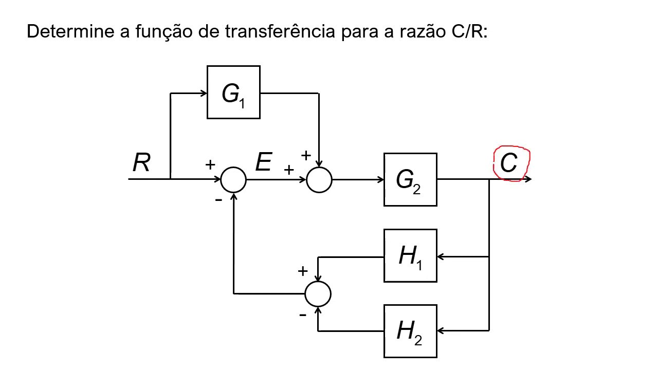
Diagramas de blocos e sua álgebra

PCSI - video 3 - SLCI cours asservissements - Partie2 : FT et schema blocs
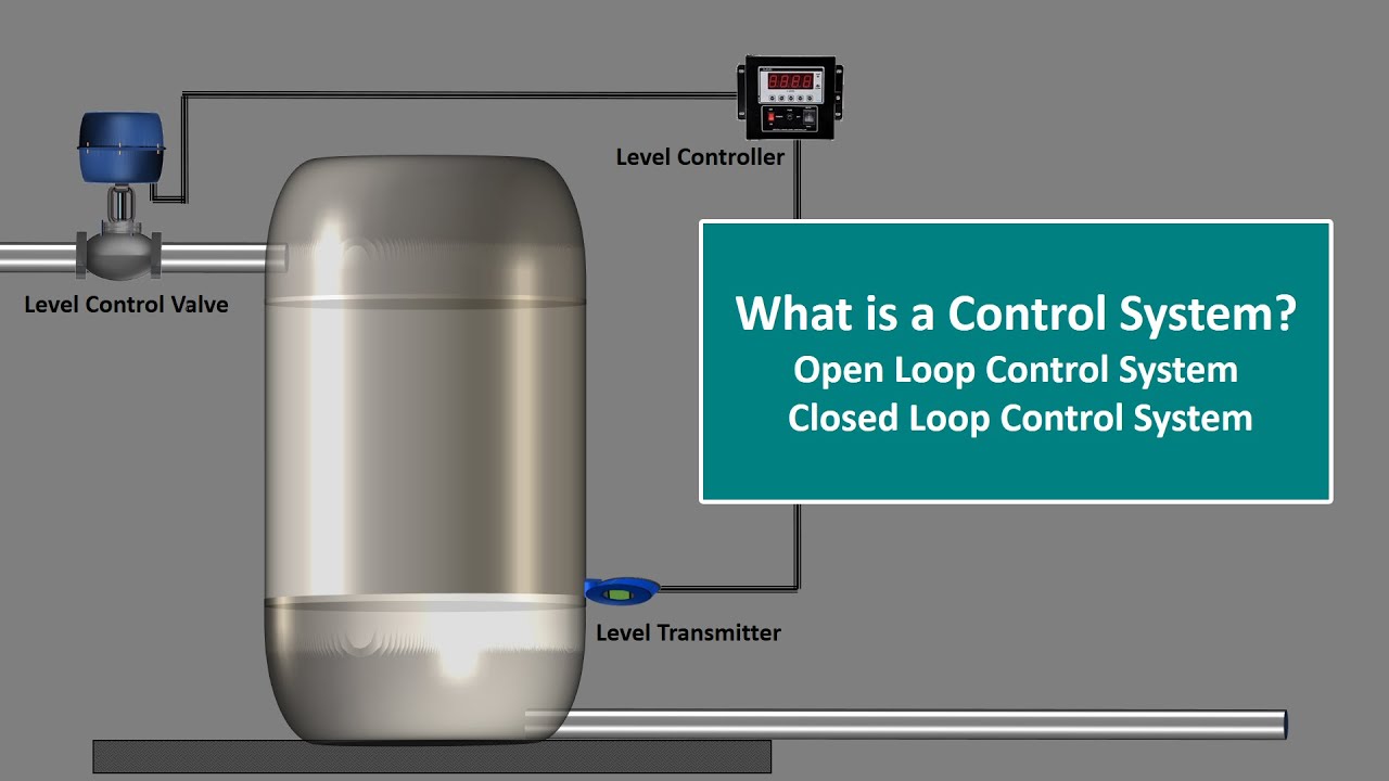
What is Control System.Control System Engineering.Open Loop and Closed Loop Control System.Explained
06. MG3217 Kendali Proses S01: Penyederhanaan Diagram Blok
5.0 / 5 (0 votes)